68 YASKAWA TM.V1000.01 V1000 Drive Installation & Start-Up Manual (Preliminary 01-19-07)
3.6 Main Circuit Wiring
3.6 Main Circuit Wiring
This section describes the functions, specifications, and procedures required to
safely and properly wire the main circuit of the drive.
NOTICE: Do not solder the ends of wire connections to the drive. Soldered wiring connections
can loosen over time. Improper wiring practices could result in drive malfunction due to loose
terminal connections.
◆ Main Circuit Terminal Functions
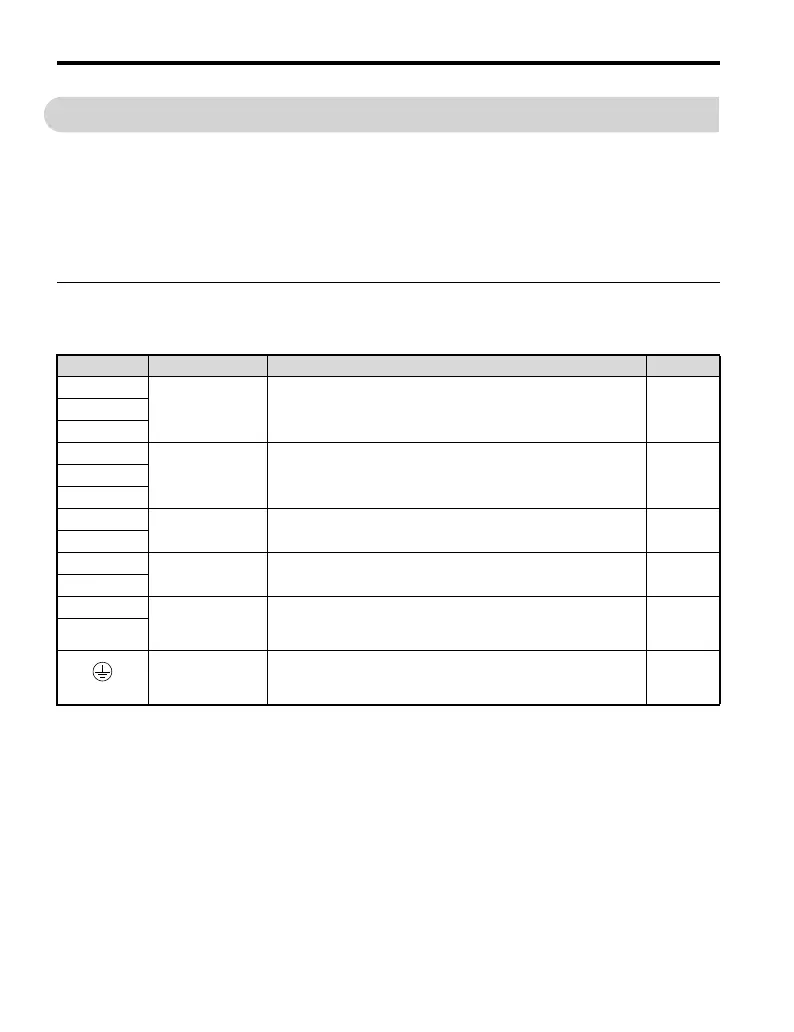
Table 3.1 Main Circuit Terminal Functions
Terminal Type Function Reference
R/L1
Main circuit power
supply input
Connects line power to the drive.
Drives with single phase 200 V input power use terminals R/L1
and S/L2 only (T/L3 must not be used).
73S/L2
T/L3
U/T1
Drive output Connects to the motor. 71V/T2
W/T3
B1
Braking resistor
Available for connecting a braking resistor or the braking resistor
unit option.
91
B2
+1
DC reactor
connection
These terminals are shorted at shipment. Remove the shorting bar
to install a DC choke.
74
297
+2
+1
DC power supply
input
For connecting a DC power supply.
Note: DC power supply input terminals (+1, –) are both UL and
EU certified.
59
–
(2 terminals)
Ground
Grounding Terminal
For 200 V class: 100 Ω or less
For 400 V class: 10 Ω or less
72

 Loading...


