3.6 Main Circuit Wiring
YASKAWA TM.V1000.01 V1000 Drive Installation & Start-Up Manual (Preliminary 01-19-07) 73
Electrical Installation
3
■ Wiring the Main Circuit Terminal
WARNING! Electrical Shock Hazard. Shut off the power supply to the drive before wiring the
main circuit terminals. Failure to comply may result in death or serious injury.
Note: 1. A protective cover is placed over option-related terminals prior to shipment.
Use a pair of needle-nose pliers to remove the protective cover.
2. The protective cover is held in place by the ground terminal screw on NEMA Type 1
models.
Main Circuit Connection Diagram
Figure 3.16 and Figure 3.17 illustrate the standard drive connection diagrams.
Connections may vary based on drive capacity.
WARNING! Fire Hazard. The braking resistor connection terminals are B1 and B2. Do not
connect braking resistors to any other terminals. Improper wiring connections could result in
death or serious injury by fire. Failure to comply may result in damage to the braking circuit or
drive.
■
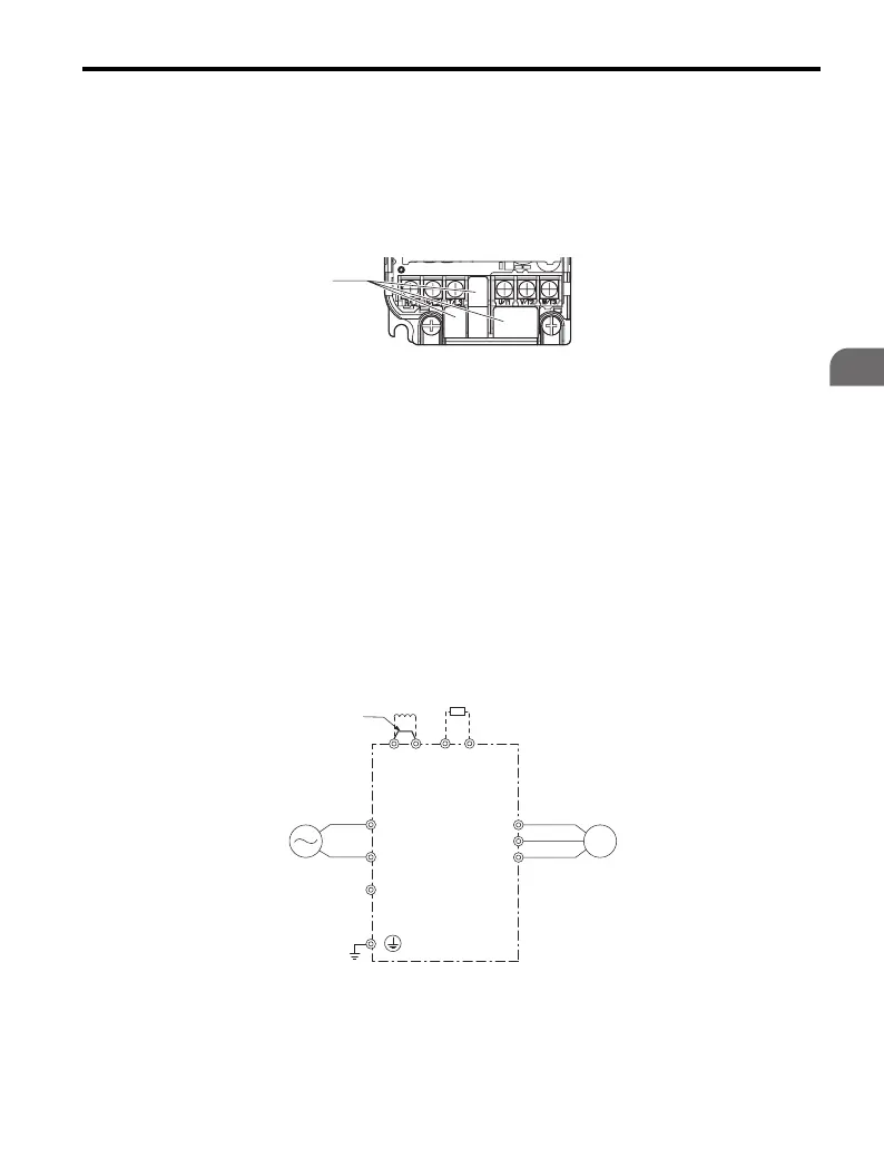
Single-Phase 200 V Class (CIMR-VBA0001 to 0012)
Figure 3.16
Figure 3.16 Connecting Main Circuit Terminals
A – Protective Terminal Cover
Drive
Jumper
Single-phase
200 Vac
Motor
DC reactor
(option)
Braking Resistor
Unit (option)
R/L1
S/L2
㧗1
㧗2
㧙
B1 B2
U/T1
V/T2
W/T3

 Loading...


