YASKAWA TM.V1000.01 V1000 Drive Installation & Start-Up Manual (Preliminary 01-19-07) 59
3.3 Main Circuit Connection Diagram
Electrical Installation
3
3.3 Main Circuit Connection Diagram
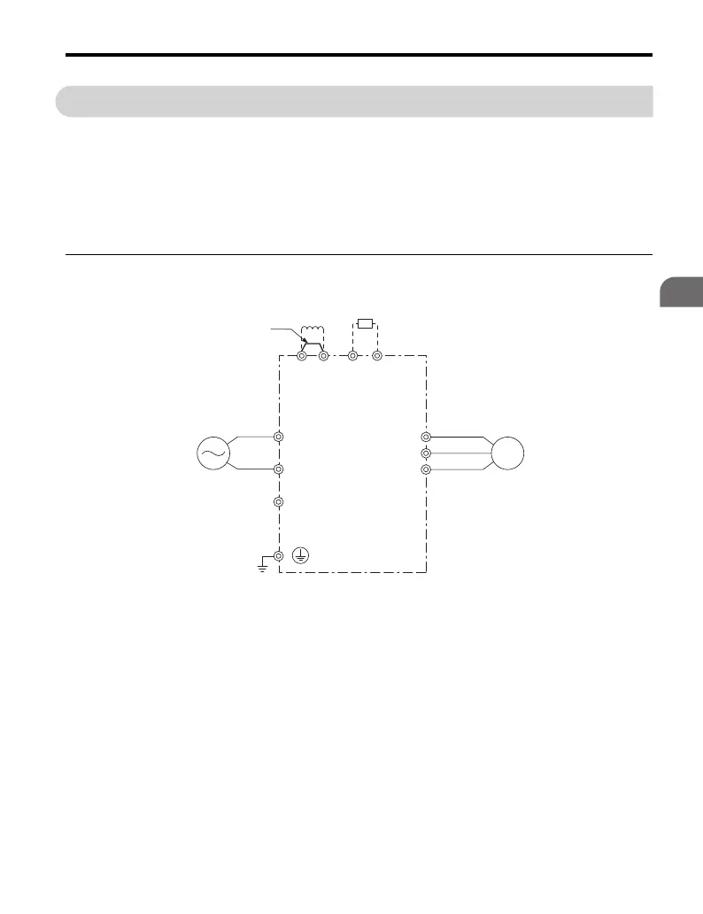
Refer to Figure 3.3 and Figure 3.4 for standard drive connection diagrams.
Connections may vary based on drive capacity. The main circuit DC power supply
powers the control circuit.
NOTICE: Do not use the negative DC bus terminal “-” as a ground terminal. This terminal is at
high voltage DC potential. Improper wiring connections could result in damage to the drive.
◆ Single-Phase 200 V Class (CIMR-VBA0001 to 0020)
Figure 3.3
Figure 3.3 Connecting Main Circuit Terminals
Drive
Jumper
Single-phase
200 Vac
Motor
DC reactor
(option)
Braking Resistor
Unit (option)
R/L1
S/L2
㧗1
㧗2
㧙
B1 B2
U/T1
V/T2
W/T3

 Loading...


