YASKAWA TM.V1000.01 V1000 Drive Installation & Start-Up Manual (Preliminary 01-19-07) 61
3.4 Terminal Block Configuration
Electrical Installation
3
3.4 Terminal Block Configuration
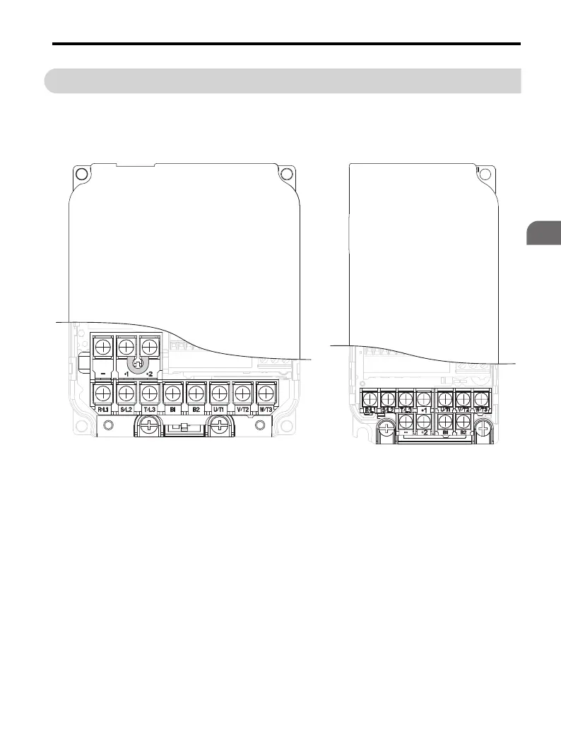
The figures in this section provide quick reference detailed illustrations of the main
and control circuit terminal block configurations.
Figure 3.5
Figure 3.5 Main Circuit Terminal Block Configurations
Models CIMR-VBA0006, 0010, 0012
Models CIMR-V
BA0001,
CIMR-V
2A0010, 0012, 0020
CIMR-V4A0001, 0002, 0004, 0005,
0007, 0009, 0011
0002, 0003
CIMR-V
2A0001, 0002,
0004, 0006

 Loading...


