3.6 Main Circuit Wiring
YASKAWA TM.V1000.01 V1000 Drive Installation & Start-Up Manual (Preliminary 01-19-07) 69
Electrical Installation
3
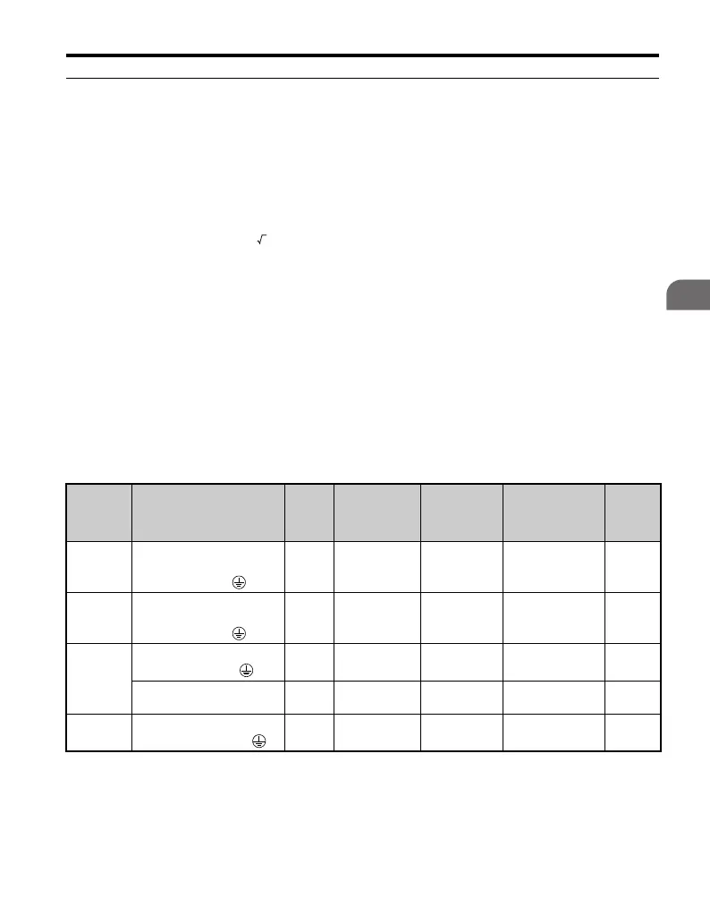
◆ Wire Gauges and Tightening Torque
Select the appropriate wires and crimp terminals from Table 3.2 through Ta ble 3.5.
• Consider the amount of voltage drop when selecting wire gauges.
Increase the wire gauge when the voltage drop is greater than 2% of motor rated
voltage. Ensure the wire gauge is suitable for the terminal block. Use the
following formula to calculate the amount of voltage drop:
• Line drop voltage (V) =
• 3 x wire resistance (Ω/km) x wire length (m) x current (A) x 10
-3
Refer to instruction manual TOBPC72060000 for braking unit or braking
resistor unit wire gauges.
• Refer to Standards Compliance on page 435 for information on UL compliance.
Note: 1. Wire gauge recommendations based on drive continuous current ratings using 75°C 600
Vac vinyl-sheathed wire assuming ambient temperature within 30°C and wiring distance
less than 100 m.
2. Terminals +1, +2, –, B1 and B2 are for connecting optional devices such as a DC reactor or
braking resistor. Do not connect other non-specified devices to these terminals.
■
Single-Phase 200 V Class
Table 3.2 Wire Gauge and Torque Specifications
Model
CIMR-
VBA
Terminal
Screw
Size
Tightening
Torque
N•m
(lb.in.)
Applicable
Gauge
mm
2
(AWG)
Recommended
Gauge
mm
2
(AWG)
Line
Type
0001
0002
0003
R/L1, S/L2,
U/T1, V/T2, W/T3,
–, +1, +2, B1, B2,
M3.5
0.8 to 1.0
(7.1 to 8.9)
0.75 to 2.00
(18 to 14)
2.5
(14)
Note: 1.
0006
R/L1, S/L2,
U/T1, V/T2, W/T3,
–, +1, +2, B1, B2,
M4
1.2 to 1.5
(10.6 to 13.3)
2.0 to 5.5
(14 to 10)
2.5
(14)
Note: 1.
0010
R/L1, S/L2,
U/T1, V/T2, W/T3,
M4
1.2 to 1.5
(10.6 to 13.3)
2.0 to 5.5
(14 to 10)
4
(12)
Note: 1.
–, +1, +2, B1, B2, M4
1.2 to 1.5
(10.6 to 13.3)
2.0 to 5.5
(14 to 10)
6
(10)
Note: 1.
0012
R/L1, S/L2, U/T1, V/T2, W/
T3, –, +1, +2, B1, B2,
M4
1.2 to 1.5
(10.6 to 13.3)
2.0 to 5.5
(14 to 10)
6
(10)
Note: 1.

 Loading...


