B.2 Parameter Table
404 YASKAWA TM.V1000.01 V1000 Drive Installation & Start-Up Manual (Preliminary 01-19-07)
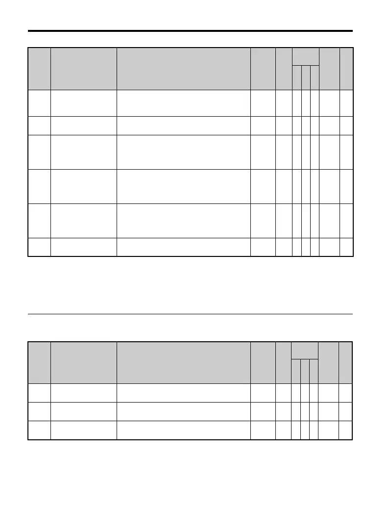
◆ r: DWEZ Parameters
o4-07
Inrush Prevention
Relay Maintenance
Setting
Resets the Inrush Prevention Relay
Maintenance Time to 0 (U4-06).
0 to 150 0% A A A 523 —
o4-09
IGBT Maintenance
Setting
Resets the counter that logs the IGBTs usage
time. Refer to U4-07 (IGBT Maintenance).
0 to 150 0% A A A 525 —
o4-10
IGBT Maintenance
Setting
Displays “LT-4” when the maintenance period
is passed, activates a multi-function output
(H2- = 10 or 2F) (this display can be
changed during run).
0 to
150%
50% A A A 526 —
o4-11
U2, U3 Initial Value
Selection
0: Saves the value for U2- (Fault Trace)
and U3- (Fault History).
1: Resets the values for U2- (Fault Trace) and
U3- (Fault History).
0 to 1 0 A A A 510 —
o4-12
kWH Monitor Initial
Value Selection
0: Saves the values of monitor parameters
U4-10 and U4-11.
1: Resets monitor parameters U4-10 and U4-11
back to default settings.
0 to 1 0 A A A 512 —
o4-13 Motor r/min Reset
0: Maintain the current r/min.
1: Reset the number of motor revolutions to 0.
0 to 1 0 A A A 528 —
<9> Default setting value is dependent on parameter E1-01, Input Voltage Setting.
<11> Default setting value is dependent on parameter o1-03, Digital Operator Display Selection.
<12> Default setting value is dependent on parameter o2-04, Drive/kVA Selection.
<14> Default setting value is dependent on parameter o2-09, Initialization Spec. Selection.
<22> Parameter can be changed during run.
No. Name Description Range Def.
Control
Mode
Addr.
Hex
Pg.
V/
f
O
L
V
P
M
r1-01
DWEZ Connection
Parameter 1 (upper)
Parameter 1 for connecting DWEZ (upper).
0 to
FFFFH
0 – A A 1840 —
r1-02
DWEZ Connection
Parameter 1 (lower)
Parameter 1 for connecting DWEZ (lower).
0 to
FFFFH
0 – A A 1841 —
r1-03
DWEZ Connection
Parameter 2 (upper)
Parameter 2 for connecting DWEZ (upper).
0 to
FFFFH
0 – A A 1842 —
No. Name Description Range Def.
Control
Mode
Addr.
Hex
Pg.
V/
f
O
L
V
P
M

 Loading...


