C.1 MEMOBUS/Modbus Basic Set-Up
432 YASKAWA TM.V1000.01 V1000 Drive Installation & Start-Up Manual (Preliminary 01-19-07)
◆ Communication Set-Up Procedure
Use the following procedure to communicate with the PLC.
1. Turn OFF the input to the drive power and connect the communication
cable between the PLC (or other master device) and the drive.
2. Turn ON the input power to the drive.
3. Set the required communication parameters (H5-01 to H5-07) using the
Digital Operator.
4. Turn OFF the input to the drive power, and check that the Digital Operator
display has completely extinguished.
5. Turn ON the input power to the drive once again.
6. Perform communication with the master device.
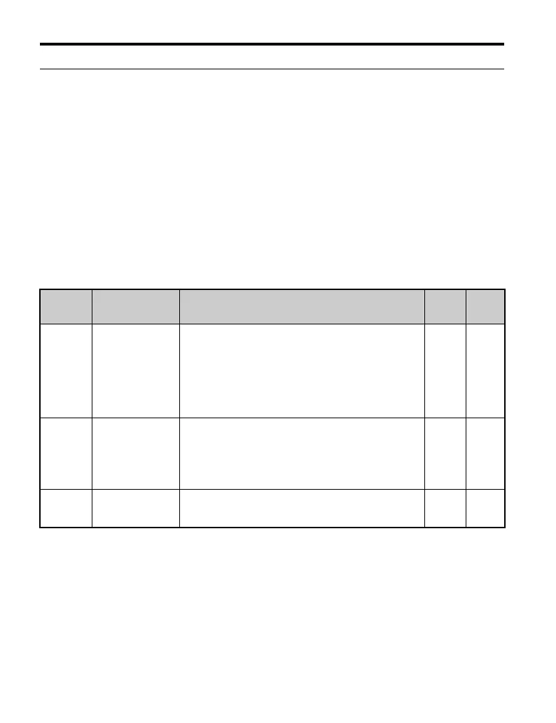
Table C.4 Serial Communication Related Parameters
Parameter
No.
Parameter Name
Digital Operator
Display
Description
Setting
Range
Factory
Setting
b1-01
Frequency
Reference
Selection
Reference Source
Selects the frequency reference input source.
0: Operator - Digital preset speed U1-01 or d1-01 to d1-17.
1: Terminals - Analog input terminal A1 (or terminal A2
based on parameter H3-09).
2: Serial Com - MEMOBUS/Modbus RS-422/485 terminals
R+, R-, S+ and S-.
3: Option PCB
4: Pulse Input (Terminal RP)
0 to 4 1
b1-02
Run Command
Selection
Run Source
Selects the run command input source.
0: Operator - RUN and STOP keys on the digital operator.
1: Terminals - Contact closure on terminals S1 or S2.
2: Serial Com - MEMOBUS/Modbus RS-422/485 terminals
R+, R-, S+ and S-.
3: Option PCB.
0 to 3 1
H5-01
Drive Node Address
Serial Comm Adr
Selects drive station node number (address) for MEMOBUS/
Modbus terminals R+, R-, S+, S-. Cycle power for the
setting to take effect.
0 to 20
Hex
1F

 Loading...


