3.7 Control Circuit Wiring
80 YASKAWA TM.V1000.01 V1000 Drive Installation & Start-Up Manual (Preliminary 01-19-07)
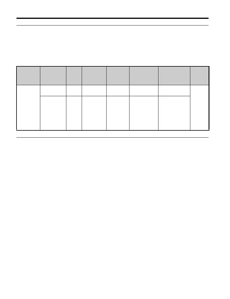
◆ Wire Size and Torque Specifications
Select the appropriate wires and crimp terminals from Tab le 3.9.
■ Wire Size and Torque Specifications
Table 3.9 Wire Size and Torque Specifications (Same for All Models)
◆ Wiring Procedure
This section describes the proper procedures and preparations for wiring the
terminal board.
WARNING! Electrical Shock Hazard. Do not remove covers or touch the circuit boards while
the power is on. Failure to comply could result in death or serious injury.
NOTICE: Separate control circuit wiring from main circuit wiring (terminals R/L1, S/L2, T/L3,
B1, B2, U/T1, V/T2, W/T3, 1, 2 and 3) and other high-power lines. Improper wiring practices
could result in drive malfunction due to electrical interference.
NOTICE: Separate wiring for digital output terminals MA, MB and MC from wiring to other
control circuit lines. Improper wiring practices could result in drive or equipment malfunction or
nuisance trips.
NOTICE: Use a class 2 power supply (UL standard) when connecting to the control terminals.
Improper application of peripheral devices could result in drive performance degradation due
to improper power supply.
NOTICE: Insulate shields with tape or shrink tubing to prevent contact with other signal lines
and equipment. Improper wiring practices could result in drive or equipment malfunction due to
short circuit.
Attachment Terminal
Screw
Size
Tightening
Torque
Nxm
Tightening
Torque
(in-lbs)
Applicable
wire size
mm
2
(AWG)
Recommended
mm
2
(AWG)
Wire
Type
Screw Type
(standard)
MA, MB, MC M3 0.5 to 0.6 4.4 to 5.3
0.25 to 1.25
(24 to 16)
0.75 (18)
Shielded
line, etc.
S+, S-, R+,
R-, IG, SC,
S1-S7, P1,
P2, PC, MP,
RP, AM, +V,
A1, A2, AC,
HC, H1
M2 0.22 to 0.25 1.9 to 2.2
Stranded wire:
0.25 to 0.75
(24 to 18)
Single wire:
0.25 to 1.25
(24 to 16)
0.75 (18)

 Loading...


