3.7 Control Circuit Wiring
YASKAWA TM.V1000.01 V1000 Drive Installation & Start-Up Manual (Preliminary 01-19-07) 79
Electrical Installation
3
■ Serial Communication Terminals
Table 3.8 Control Circuit Terminals: Serial Communications
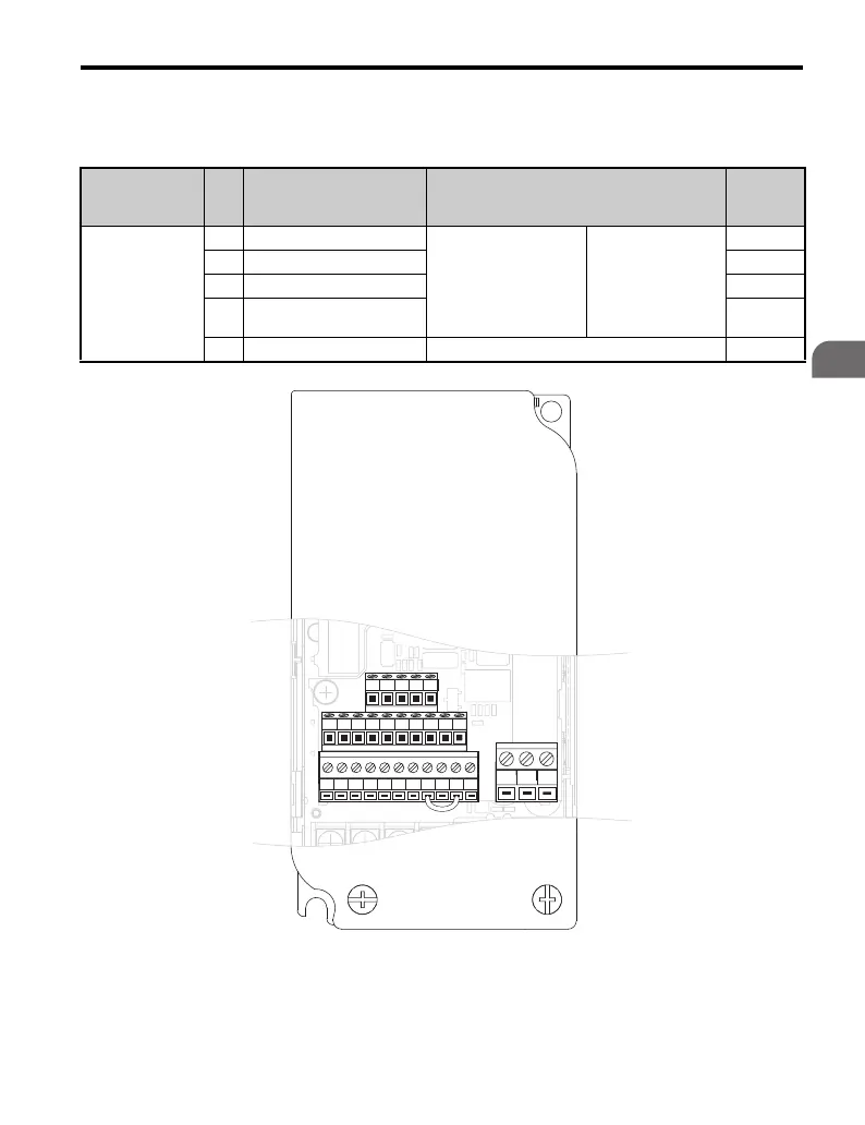
Figure 3.20
Figure 3.20 Control Circuit Terminal Block Configuration
(CIMR-VA; CIMR-VU)
Type No. Signal Name
Function (Signal Level)
Default Setting
Reference
MEMOBUS/
Modbus
Communication
R+ Communications input (+)
MEMOBUS/Modbus
communication:
Use a RS-485 or
RS-422 cable to connect
the drive.
RS-485/422
MEMOBUS/
Modbus
communication
protocol
115.2 kBps (max.)
—
R– Communications input (–) —
S+ Communications output (+) —
S- Communications output (–) —
IG Shield ground 0 V —
S1 S2 S3 S4 S5 S6 S7 HC SC H1 RP
R+ R
㧙
S+ S
㧙
IG
P1 P2 PC A1 A2 +V AC AM AC MP
MCMBMA

 Loading...


