4.2 Using the Digital LED Operator
YASKAWA TM.V1000.01 V1000 Drive Installation & Start-Up Manual (Preliminary 01-19-07) 117
Start-Up Programming &
Operation
4
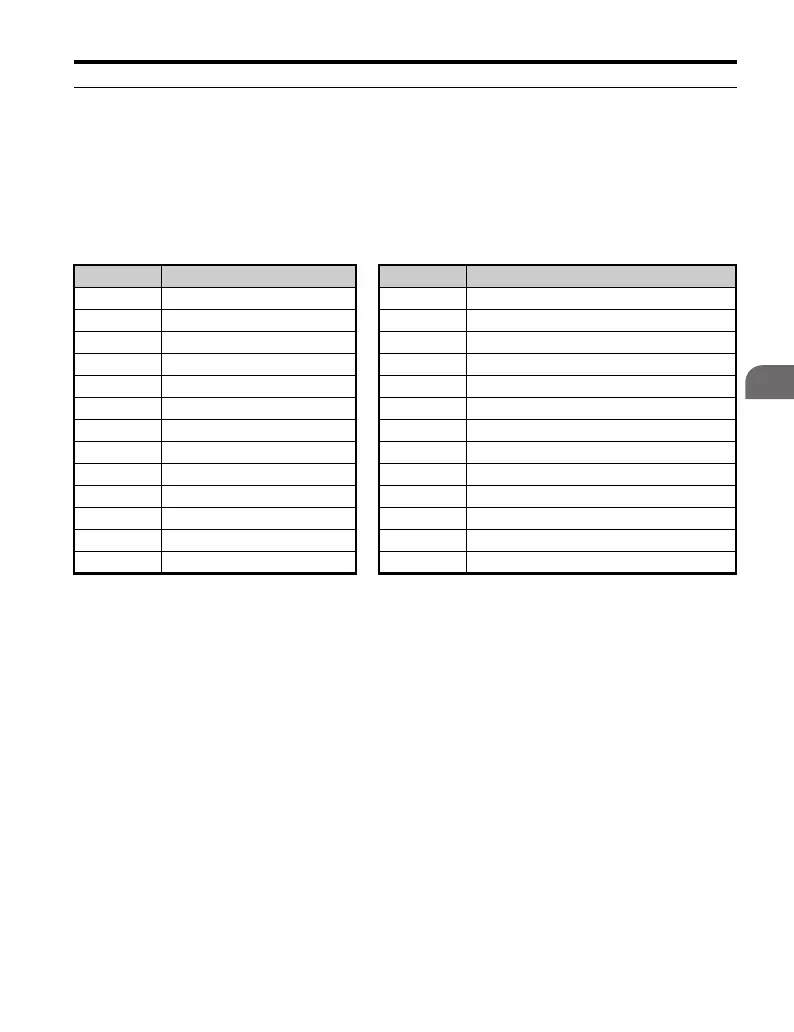
◆ Parameters Available in the Setup Group
Table 4. 4 lists parameters available in the Setup Group. This manual also explains
other parameters that are not visible in the Setup Group. The “Par” menu in the
Programming mode must be used to access other parameters not listed in the Setup
Group. The Setup Group parameters are shown in Table 4.4.
Table 4.4 Setup Group Parameters
Parameter Name Parameter Name
A1-02 Control Method Selection d1-17 Jog Frequency Reference
A1-06 Preset Application Selection E1-01 Input Voltage Reference
b1-01 Frequency Reference Selection 1 E1-04 Maximum Output Frequency (FMAX)
b1-02 Run Command Selection 1 E1-05 Maximum Voltage (VMAX)
b1-03 Stop Method Selection E1-06 Base Frequency (FA)
C1-01 Acceleration Time 1 E1-09 Minimum Output Frequency (FMIN)
C1-02 Deceleration Time 1 E1-13 Base Voltage (VBASE)
C6-01 Duty Selection E2-01 Motor Rated Current
C6-02 Carrier Frequency Selection E2-11 Motor Rate Capacity
d1-01 Frequency Reference 1 E3-13 Motor 2 Base Voltage (VBASE)
d1-02 Frequency Reference 2 H4-02 Terminal FM Gain Setting
d1-03 Frequency Reference 3 L1-01 Motor Protection Function Selection
d1-04 Frequency Reference 4 L3-04 Stall Prevention Selection during Deceleration

 Loading...


