B.2 Parameter Table
366 YASKAWA TM.V1000.01 V1000 Drive Installation & Start-Up Manual (Preliminary 01-19-07)
◆ F: Options
F parameters are used to program the drive to function with options.
<21> Range upper limit is dependent on parameter E4-01 Motor 2 Rated Current.
<22> Parameter can be changed during run.
<24> Values shown here are for 200 V class drives. Double the value when using a 400 V class drive.
<25> Parameter setting value is not reset to the default value during drive initialization, A1-03 = 1110, 2220, 3330.
<26> Parameter ignored when E3-11, Motor 2 Mid Output Frequency 2, and E3-12, Motor 2 Mid Output Frequency
Voltage 2, are set to 0.0.
<27> Setting units for this parameter are determined by o2-04, Drive/kVA Selection. Less than 11 kW: 2 decimal
points, 11 kW and above: 1 decimal point.
<28> When parameter A1-02 = 5-PM OLV Control, E3-13 Motor 2 Base Voltage will be equal to T1-03, Motor Rated
Voltage, after Auto-Tuning the drive
<35> Default setting is determined by the V/f pattern selected to parameter E1-03.
<36> Default setting changes when using OLV Control for PM motors.
<37> Setting range becomes 0.00 to 130.00 for drives 0.2 kW and smaller.
<38> If using a Yaskawa pico motor, the default setting is 1800 r/min.
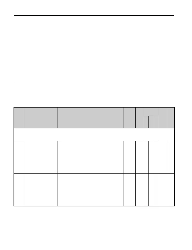
No. Name Description Range Def.
Control
Mode
Addr.
Hex
Pg.
V/
f
O
L
V
P
M
F1: Simple PG V/f Parameters
Use F1 parameters to set up the drive for Simple PG V/f control.
F1 parameters are enabled only when using Simple V/f with PG control (H6-01 = 03).
F1-02
Operation Selection at
PG Open Circuit
(PGO)
Sets stopping method when a PG open circuit
fault (PGO) occurs. Refer to parameter F1-14.
0: Ramp to Stop - Decelerate to stop using the
active deceleration time.
1: Coast to Stop
2: Fast-stop - Decelerate to stop using the
deceleration time in C1-09.
3: Alarm only - Drive continues operation.
0 to 3 1 A −− 381 —
F1-03
Operation Selection at
Overspeed (OS)
(for Simple PG V/f)
Sets the stopping method when an overspeed
(OS) fault occurs. Refer to F1-08 and F1-09.
0: Ramp to stop - Decelerate to stop using the
active deceleration time.
1: Coast to stop
2: Fast - Stop - Decelerate to stop using the
deceleration time in C1-09.
3: Alarm Only - Drive continues operation.
0 to 3 1 A −− 382 —

 Loading...


