88 YASKAWA TM.V1000.01 V1000 Drive Installation & Start-Up Manual (Preliminary 01-19-07)
3.9 Main Frequency Reference
3.9 Main Frequency Reference
◆ Terminal A2 Switch
The main frequency reference can either be a voltage or current signal input. For
voltage signals both analog inputs, A1 and A2, can be used, for current signals A2
must be used.
To use current input at terminal A2, set the DIP switch S1 to "I" (factory setting;
right) and set parameter H3-09 = “2” or “3” (4-20 mA or 0-20 mA). Set parameter
H3-10 = “0” (frequency reference).
Note: If Terminals A1 and A2 are both set for frequency reference (H3-02 = 0
and H3-10 = 0), the addition of both input values builds the frequency reference.
When using input A2 as voltage input, set the DIP switch S1 to “V” (left position)
and program parameter H3-09 accordingly.
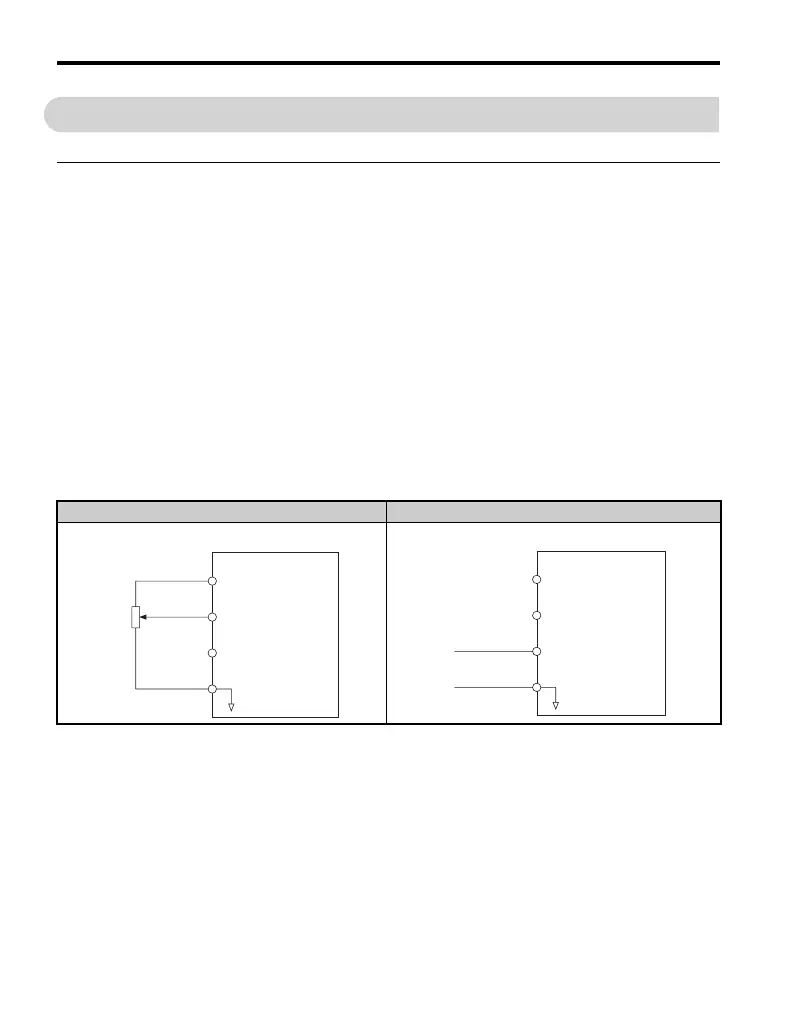
Table 3.10 Frequency Reference Configurations
Voltage Input Current Input
Drive
Main speed
frequency reference
(voltage input)
Main speed
frequency reference
(current input)
Frequency reference
common
+10.5 V
20 mA current
0 to 10 V
+V
A1
A2
AC
2 kΩ
Drive
Main speed
frequency reference
(voltage input)
Main speed
frequency reference
(current input)
Frequency reference
common
4 to 20 mA input
or
0 to 20 mA input
+10.5 V
20 mA current
+V
A1
A2
AC

 Loading...


