3.9 Main Frequency Reference
YASKAWA TM.V1000.01 V1000 Drive Installation & Start-Up Manual (Preliminary 01-19-07) 89
Electrical Installation
3
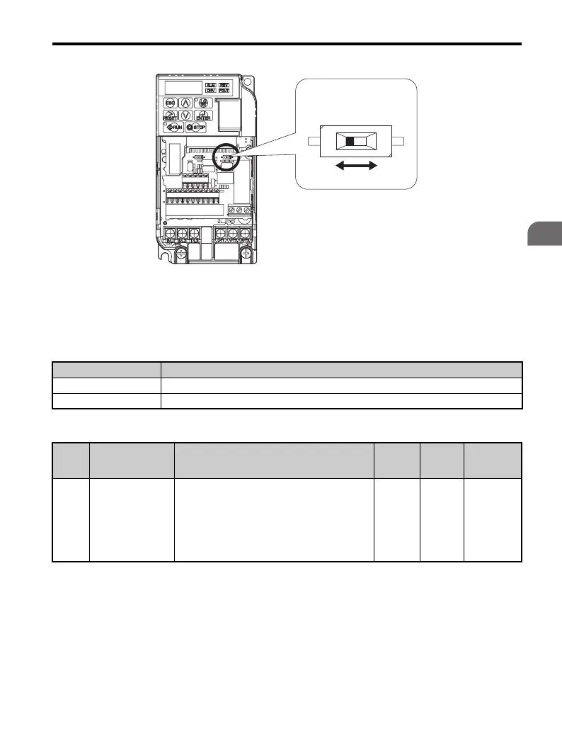
Figure 3.28
Figure 3.28 DIP Switch S1
Table 3.11 DIP Switch S1 Settings
Table 3.12 Parameter H3-09 Details
A – DIP switch S1
Setting Value Description
V (left position) Voltage input (0 to 10 V): default setting
I (right position) Current input (4 to 20 mA or 0 to 20 mA)
No. Parameter Name Description
Setting
Range
Default
Setting
MEMOBUS/
Modbus
Address
H3-09
Frequency ref.
(current)
terminal A2
signal level
selection
Selects the signal level for terminal A2.
0: 0 to +10 V, unipolar input (negative frequency
reference values are zeroed)
1: -10 to +10 V, bipolar input (negative
frequency reference changes the direction)
2: 4 to 20 mA (9-bit input)
3: 0-20 mA
0 to 3 2 417H
A
VI

 Loading...


