B.2 Parameter Table
400 YASKAWA TM.V1000.01 V1000 Drive Installation & Start-Up Manual (Preliminary 01-19-07)
◆ o: Operator Related Parameters
o parameters are used to set up the LED digital operator displays.
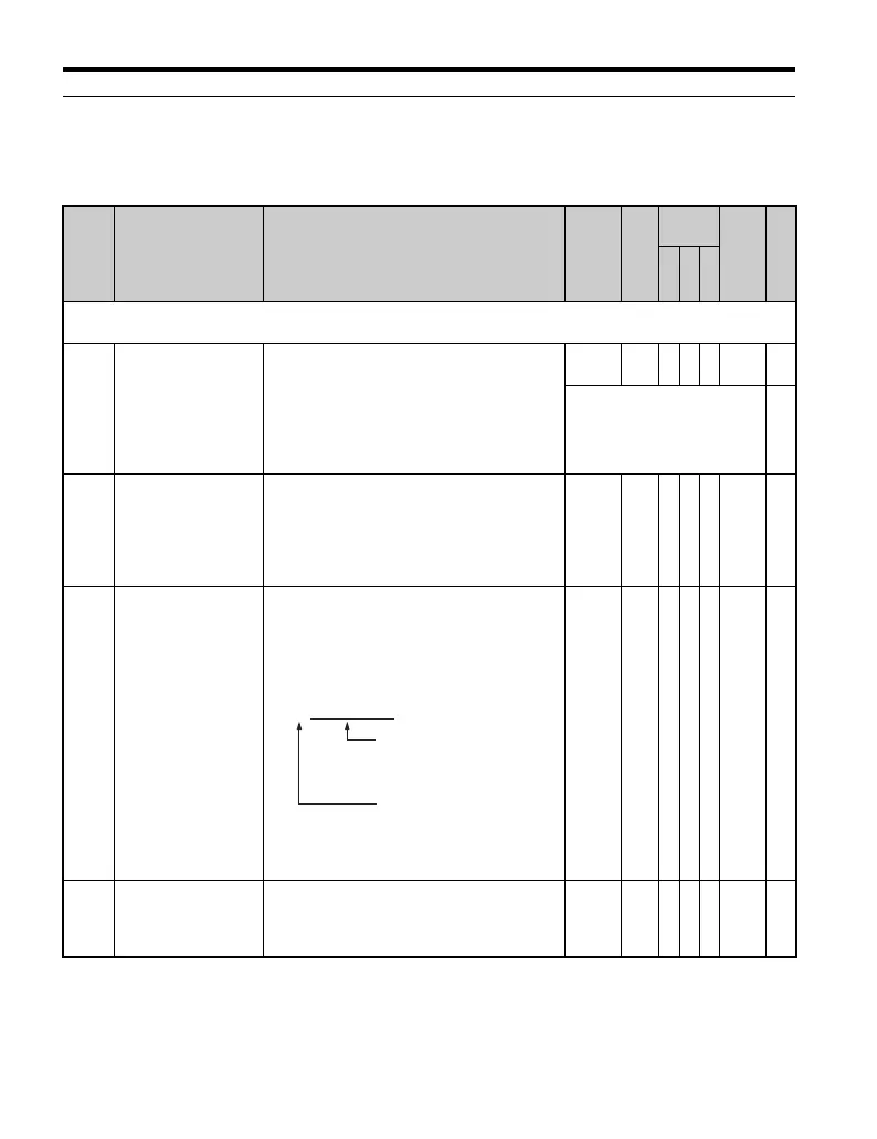
No. Name Description Range Def.
Control
Mode
Addr.
Hex
Pg.
V/
f
O
L
V
P
M
o1: Display Settings
Use o1 parameters to configure the digital operator display.
o1-01
<22>
Drive Mode Unit
Monitor Selection
Selects which monitor will be displayed in the
operation menu upon power-up when
o1-02 = 4. Press the “up” arrow key four times
and select the desired monitor. The monitor
parameter number is entered into the spaces
provided: U-. For example, set “403” to
display monitor parameter U4-03.
104 to
710
106 A A A 500 —
Set to U1-06 as a default
(Output Voltage Reference).
—
o1-02
<22>
User Monitor
Selection After Power
Up
Selects the monitor to display upon power-up.
1: Frequency Reference (U1-01)
2: Forward/Reverse
3: Output Frequency (U1-02)
4: Output Current (U1-03)
5: User Monitor (set by o1-01)
1 to 5 1 A A A 501 —
o1-03
Digital Operator
Display Selection
Sets the units to display the frequency
reference and output frequency.
0: Hz
1: % (100% = E1-04)
2: r/min (enter the number of motor poles)
For a max output frequency of 200.0, set to
12000.
0 to
39999
0AAA502—
o1-05
<22>
LED Contrast
Sets the contrast of the digital operator LED
(option). A setting of "1" is the lightest contrast
and a setting of "5" is the darkest contrast.
3: Normal contrast
0 to 5 3 A A A 504 —
غغغغغغ
o1-10: Sets the first five
digits of the value,
disregarding the
decimal point.
o1-11: Sets the number
of digits past the
decimal point

 Loading...


