YASKAWA TM.V1000.01 V1000 Drive Installation & Start-Up Manual (Preliminary 01-19-07) 75
3.7 Control Circuit Wiring
Electrical Installation
3
3.7 Control Circuit Wiring
Figure 3.18
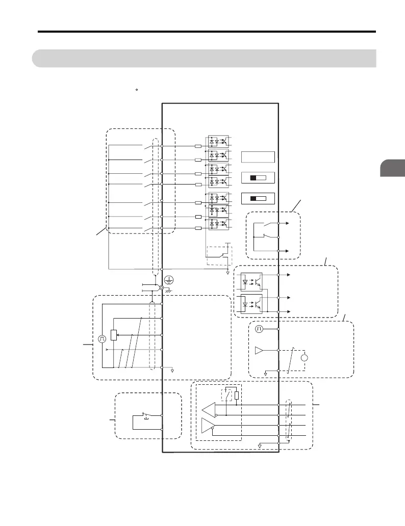
Figure 3.18 Control Circuit Connection Diagram
Shielded lines are circled with a dashed line, while twisted-pair, shielded cables have an additional cross line.
A double circle O indicates a main circuit terminal, while a single circle O indicates a control terminal.
All analog and digital I/O are programmable for multiple functions.
Additional Notes:
Forward run/stop
Reverse run/stop
External fault
Fault reset
Multi-step
speed 2
Jog reference
0 to +10 Vdc
(2 mA)
DIP
switch S3
Multi-function digital input
(standard default setting)
Comm.
connector
Hardwire
Baseblock
command
input
Hardwire
Baseblock
stop switch
Option card
connector
Fault
Drive
Shield ground
terminal
Control circuit
S1
S2
S3
S4
S5
S6
S7
*
1
24
V
0
V
MA
P1
MB
MC
VI
OFF ON
+
24
V 8
mA
*
2
SC
P2
MP
AM
AC
PC
IG
R
+
R
-
S
+
S
-
+
-
AM
HC
H1
RP
+V
A1
A2
AC
2 k
W
Pulse train input
(max. 32 kHz)
0 to +10 V (20 kW) or
-10 to +10 V
Setting power supply
+10.5 max. 20 mA
0 to +10 V (20 kW) or
-10 to +10 V
-10 to +10 V (20 kW)
4 to 20 mA (250 W)
0 to 20 mA
During Run
(photocoupler 1)
Frequency agree
(photocoupler 2)
Photocoupler
output common
Photocoupler output
48 Vdc, 50 mA or less
(default setting)
Pulse train output
0 to 32 kHz
Analog monitor
output
250 Vac (10 mA to 1 A)
30 Vdc (10 mA to 1A)
(default setting)
MEMOBUS/
Modbus comm.
RS-485/422
Frequency reference
setting potentiometer
Main speed
frequency
reference.
Multi-function
programmable
Multi-step
speed 1
main/aux switch
DIP switch S1
DIP switch S2
Sink
Source
Termination
resistor
120 W, 1/2 W
Monitor
output
CIMR-VU

 Loading...


