94 YASKAWA TM.V1000.01 V1000 Drive Installation & Start-Up Manual (Preliminary 01-19-07)
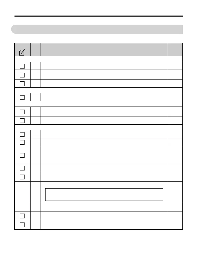
3.12 Wiring Checklist
3.12 Wiring Checklist
No. Item Page
Drive, peripherals, option cards
1 Check drive model number to ensure receipt of correct model. 23
2
Check for correct braking resistors, DC reactors, noise filters, and other peripheral
devices.
57
3 Check for correct option card model. 309
Installation area and physical setup
4 Ensure area surrounding the drive complies with specifications. 38
Power supply voltage, output voltage
5
The voltage from the power supply should fall within the input voltage specification
range of the drive.
313
6 The voltage rating for the motor should match the drive output specifications. 315
Main circuit wiring
7 Confirm proper branch circuit protection exists per National and Local codes. 56
8 Properly wire the power supply to drive terminals R/L1, S/L2 and T/L3. 59
9
Properly wire the drive and motor together.
The motor lines and drive output terminals R/T1, V/T2 and W/T3 should match in order
to produce the desired phase order. If the phase order is incorrect, the drive will rotate in
the opposite direction.
71
10 Use 600 Vac vinyl-sheathed wire for the power supply and motor lines. 69
11
Use the correct wire gauges for the main circuit. Refer to Table 3.2, Table 3.3, or
Table 3.4.
69
• When using comparatively long motor cable, calculate the amount of voltage drop.
69
• If the cable between the drive and motor exceeds 100 m, adjust the carrier frequency
(C6-02) accordingly.
71
12 Properly ground the drive. Review page 72. 72
13
Tightly fasten all terminal screws (control circuit terminals, grounding terminals).
Refer to Table 3.2, Table 3.3 or Table 3.4.
69
Motor rated voltage (V) × 0.02 ҈
3 × voltage resistance (Ω/km) × cable length (m) × motor rated current (A) × 10
-3

 Loading...


