3.12 Wiring Checklist
YASKAWA TM.V1000.01 V1000 Drive Installation & Start-Up Manual (Preliminary 01-19-07) 95
Electrical Installation
3
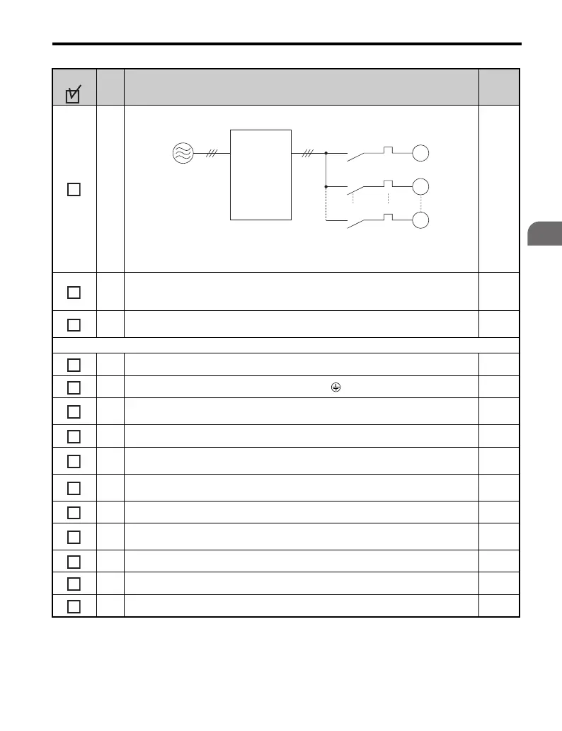
14
Set up overload protection circuits when running multiple motors from a single drive.
Note: Close MC1 through MCn before operating the drive.
15
If using a braking resistor or dynamic braking resistor unit, install a magnetic contactor.
Properly install the resistor, and ensure that overload protection shuts off the power
supply. Refer to Peripheral Devices & Options on page 289
289
16
Verify phase advancing capacitors are NOT installed on the output side of the drive.
Install an EMI/RFI noise filter on the drive input side as needed.
Control circuit wiring
17 Use twisted-pair cables for all drive control circuit wiring. 75
18
Ground the shields of shielded wiring to the GND terminal.
83
19
If using a 3-wire sequence, properly set parameters for multi-function contact input
terminals S1 through S7, and properly wire control circuits.
58
20 Properly wire any option cards. 310
21
Check for any other wiring mistakes.
Only use a multimeter to check wiring.
82
22
Properly fasten the control circuit terminal screws in the drive.
Refer to Table 3.2, Table 3.3 or Table 3.4.
69
23 Pick up all wire clippings.
24
Ensure that no frayed wires on the terminal block are touching other terminals or
connections.
25 Properly separate control circuit wiring and main circuit wiring.
26 Analog signal line wiring should not exceed 100 m.
27 All other wiring should be less than 10 m.
No. Item Page
M1
OL1
OL2
OLn
MC1
MC2
MCn
M2
Mn
Drive
MC1 - MCn
OL1 - OLn
... magnetic contacto
... thermal relay
Power supply

 Loading...


