3.7 Control Circuit Wiring
YASKAWA TM.V1000.01 V1000 Drive Installation & Start-Up Manual (Preliminary 01-19-07) 83
Electrical Installation
3
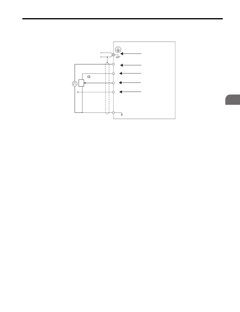
Figure 3.23
Figure 3.23 Wiring the Frequency Reference to
the Control Circuit Terminals (External Reference)
A – Drive E – (A1) Main speed frequency
reference
-10 to +10 V (20 kΩ)/
0 to +10 V (20Ω)
B – Ground terminal
(shield connection)
F – (A2) Multi-function analog
input
-10 to +10 V (20 kΩ)/
0 to +10 V (20 kΩ) or
4 to 20 mA (250 Ω)/
0 to 20 mA (250 Ω)
C – (RP) Pulse train
(maximum 32 kHz)
G – Frequency setting
potentiometer
D – (+V) Frequency setting power
source +10.5 V maximum
20 mA
H – Unused
2 k
RP
+V
A1
A2
AC
A
B
C
D
E
F
G
H

 Loading...


