3.7 Control Circuit Wiring
82 YASKAWA TM.V1000.01 V1000 Drive Installation & Start-Up Manual (Preliminary 01-19-07)
Figure 3. 22
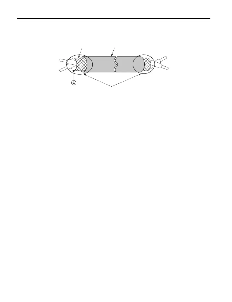
Figure 3.22 Preparing the Ends of Shielded Twisted-Pair Cables
2. Ensure that the terminal board is fastened back into place after wiring is
complete. Refer to Wire Gauges and Tightening Torque on page 69 for
tightening torque specifications.
3. Use a multimeter to check for wiring mistakes.
Use shielded twisted-pair wires for analog signal references. Ground the shield of
twisted-pair wires to the ground terminal of the drive.
NOTICE: The analog signal lines between the drive and the operator station or peripheral
equipment should not exceed 50 meters when using an analog signal from a remote source to
supply the frequency reference. Failure to comply could result in poor system performance.
A – Drive side D – Control device side
B – Shield E – Shield sheath
(Insulate with tape)
C – Insulation F – Connect shield to ground
terminal of drive
B
C
D
E
F

 Loading...


