3.7 Control Circuit Wiring
YASKAWA TM.V1000.01 V1000 Drive Installation & Start-Up Manual (Preliminary 01-19-07) 81
Electrical Installation
3
NOTICE: Connect the shield of shielded cable to the appropriate ground terminal. Improper
equipment grounding could result in drive or equipment malfunction or nuisance trips.
NOTICE: Do not tighten screws beyond the specified tightening torque. Failure to comply may
damage the terminal block.
NOTICE: Use shielded twisted-pair cables as indicated to prevent operating faults. Improper
wiring practices could result in drive or equipment malfunction due to electrical interference.
■
Wiring Procedure
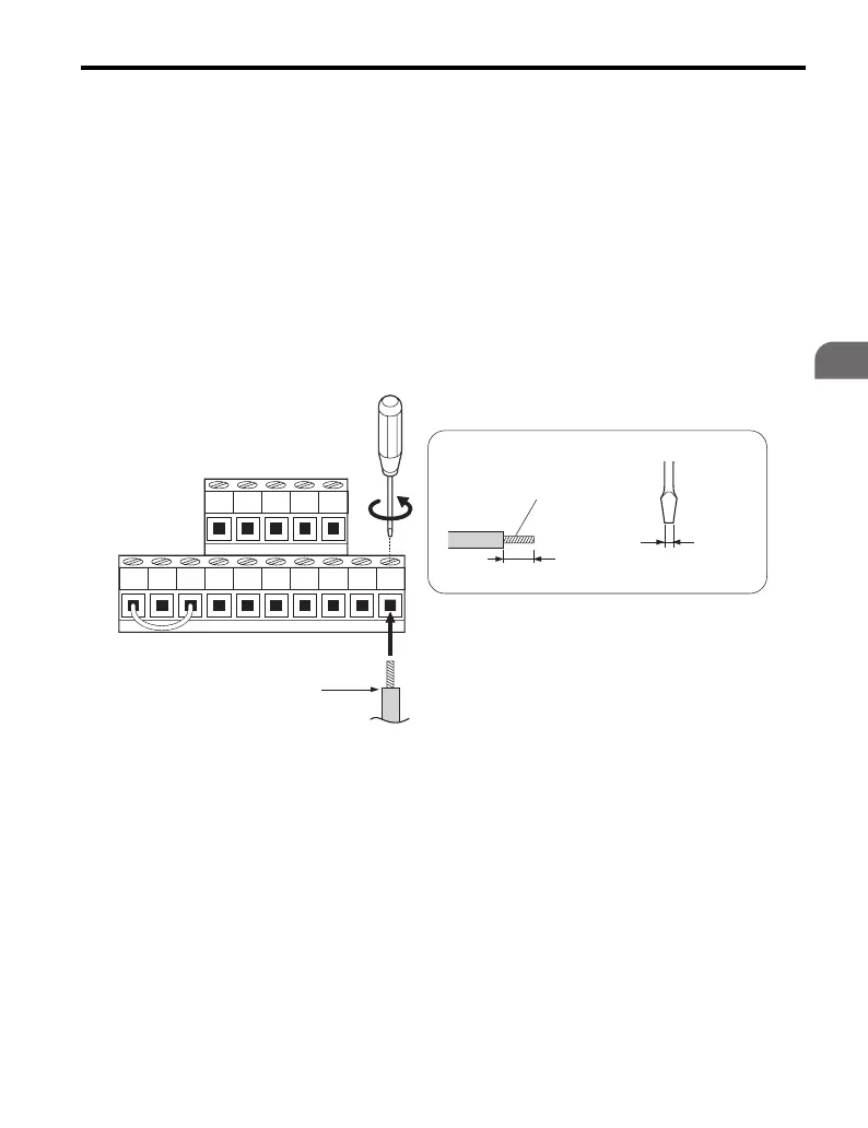
1. Wire the terminal board using Figure 3.21 as a guide (control circuit
terminal block). Be sure to prepare the ends of the control circuit wiring as
shown in Figure 3.22. Refer to Wire Gauges and Tightening Torque on
page 69 for tightening torque specifications.
Figure 3.21
Figure 3.21 Terminal Board Wiring Guide
A – Control terminal block E – Blade depth of 0.6 mm or less.
Blade width of 2.5 mm or less.
B – Preparing wire terminal ends F – Loosen the screw to insert the
wire.
C – Avoid fraying wire strands
when stripping insulation from
the wire. Strip length is 5 mm.
G – Non-soldered wire end
D – Size of screwdriver blade H –
D
A
B
C
F
E
G

 Loading...


