332 YASKAWA TM.V1000.01 V1000 Drive Installation & Start-Up Manual (Preliminary 01-19-07)
B.1 Parameter Groups
B.1 Parameter Groups
Parameter
Group
Name Page
Parameter
Group
Name Page
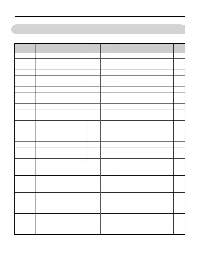
A1 Initialization 333 H4 Analog Outputs 379
A2 User Parameters 334 H5 Serial Communications Setup 379
b1 Sequence 335 H6 Pulse Train I/O Setup 381
b2 DC Injection Braking 337 L1 Motor Overload 382
b3 Speed Search 338 L2 Power Loss Ride-Thru 383
b4 Delay Timer 339 L3 Stall Prevention 384
b5 PID Control 340 L4 Reference Detection 387
b6 Dwell Function 343 L5 Fault Restart 388
b8 Energy Saving 343 L6 Overtorque Detection 390
C1 Acceleration/Deceleration Time 344 L7 Torque Limit 393
C2 S-Curve Accel/Decel 345 L8 Hardware Protection 393
C3 Motor Slip Compensation 346 n1 Hunting Prevention 396
C4 Motor Torque Compensation 347 n2 Speed Feedback Protection 397
C5 Speed Control (ASR) 348 n3 High-Slip Braking 397
C6 Carrier Frequency 348 n6
Motor Line-to-Line Resistance
Online Tuning
398
d1 Frequency Reference 350 n8 PM Motor Control 399
d2 Reference Limits 352 o1 Monitor Display Selection 400
d3 Jump Frequencies 352 o2 Key Selection 401
d4 Frequency Reference Hold 353 o4 Maintenance Time 403
d7 Off-Set Frequency 354 q DriveWorksEZ Parameters 404
E1 V/f Pattern 355 r DriveWorksEZ Connection 404
E2 Motor Setup 358 T1 Auto-Tuning 407
E3 Motor 2 V/f Pattern 360 U1 Status Monitor 408
E4 Motor Setup 2 361 U2 Fault Trace 411
E5 PM Motor Setup 364
U3 Fault History 413
F1
Fault Detection during PG Speed
Control
366 U4 Maintenance Monitor 415
F6 Network Communications 368 U5 Application Monitor 418
H1 Digital Inputs 368 U6 Control Monitor 418
H2 Digital Outputs 373 U8
Custom Monitors for
DriveWorksEZ
419
H3 Analog Inputs 377

 Loading...


