B.2 Parameter Table
YASKAWA TM.V1000.01 V1000 Drive Installation & Start-Up Manual (Preliminary 01-19-07) 381
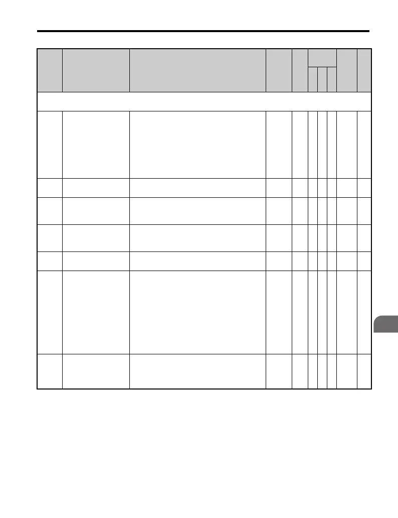
Parameter List
B
H6: Pulse Train Input/Output
Use H6 parameters to configure Pulse Train I/O operation.
H6-01
(Terminal RP) Pulse
Train Input Function
Selection
Selects the function of pulse train (terminal
RP).
0: Frequency reference
1: PID feedback value
2: PID setpoint value
3: Simple PG V/f control mode (can be set
only when using motor 1 in the V/f control
mode)
0 to 3 0 A A A 42C —
H6-02
<22>
Pulse Train Input
Scaling
Sets the number of pulses (Hz) that is equal to
the maximum output frequency E1-04.
1000 to
32000
1440
Hz
A A A 42D —
H6-03
<22>
Pulse Train Input
Gain
Sets the output level when the pulse train input
is at 100% as a percentage of maximum output
frequency (E1-04).
0.0 to
1000.0
100.
0%
AAA 42E —
H6-04
<22>
Pulse Train Input Bias
Sets the output level when the pulse train input
is 0 Hz as a percentage of maximum output
frequency (E1-04).
-100.0
to
+100.0
0.0
%
A A A 42F —
H6-05
<22>
Pulse Train Input
Filter Time
Sets the pulse train input filter time constant in
seconds.
0.00 to
2.00
0.10
s
A A A 430 —
H6-06
<22>
(Terminal MP) Pulse
Train Monitor
Selection
Select the pulse train monitor output (terminal
MP) function (value of the - part of
U-). Refer to U: Monitors on page 408
for the list of U monitors.
Example: To select U5-01, set “501.”
Displays the relationship between speed and
PID.
When not using this parameter or when using
in the through mode, set “000”.
000,
031,
101,
102,
105,
116,
501,
502,
801 to
809
102 A A A 431 —
H6-07
<22>
Pulse Train Monitor
Scaling
Sets the number of output pulses when the
monitor is 100% (in Hz). Set H6-06 to “2” and
H6-07 to “0”, to make the pulse train monitor
output equal to the output frequency.
0 to
32000
1440
Hz
A A A 432 —
<22> Parameter can be changed during run.
<39> If this parameter is set to 0, the drive will be unable to respond to MEMOBUS/Modbus commands.
<40> The availability of certain functions depends on the control method used.
No. Name Description Range Def.
Control
Mode
Addr.
Hex
Pg.
V/
f
O
L
V
P
M

 Loading...


