YASKAWA TM.V1000.01 V1000 Drive Installation & Start-Up Manual (Preliminary 01-19-07) 91
3.11 Braking Resistor
Electrical Installation
3
3.11 Braking Resistor
Dynamic braking (DB) helps bring the motor to a smooth and rapid stop when
working with high inertia loads. As the drive lowers the frequency of a motor with
high inertia connected, regeneration occurs. This can cause an overvoltage situation
when the regenerative energy flows back into the DC bus capacitors. A braking
resistor prevents these overvoltage faults.
Note: The braking circuit must be sized properly in order to dissipate the power required to
decelerate the load in the desired time. Ensure that the braking circuit can dissipate
the energy for the set deceleration time prior to running the drive.
Use a thermal overload relay or an over-temperature contact to interrupt input
power to the drive in the event the braking resistor overheats.
In the event of a possible thermal overload, the relay will trigger the magnetic
contactor and prevent the braking resistor from burning up. Use a surge protector
on the relay coil for more protection.
WARNING! Fire Hazard. The braking resistor connection terminals are B1 and B2. Do not
connect a braking resistor directly to any other terminals. Improper wiring connections could
result in death or serious injury by fire. Failure to comply may result in damage to the braking
circuit or drive.
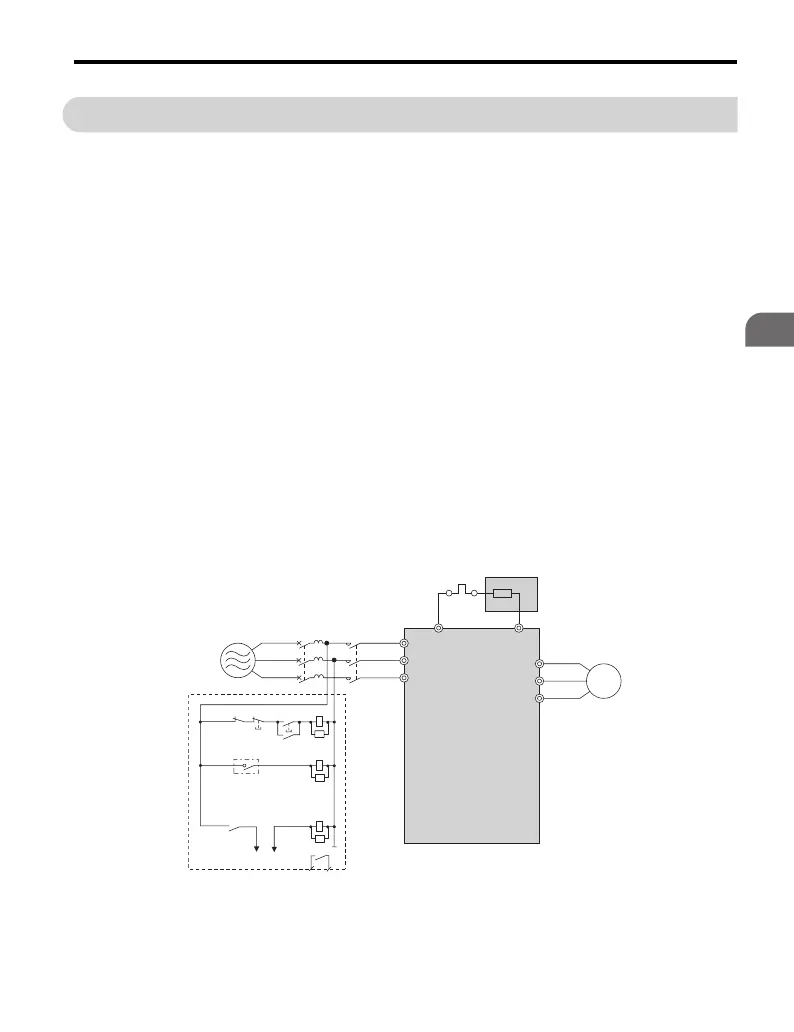
Figure 3.30
Figure 3.30 Connecting a Braking Resistor
Power
supply
Thermal
relay
Motor
Drive
Braking resistor
Thermal relay switch for
external braking resistor
Fault contact
MC
SA
SA
SA
MCON
MC
OFFTHRX
THRX
TRX
MC
TRX
FLT-A FLT-B
R/L1
B1 B2
S/L2
T/L3
U/T1
V/T2
W/T3
MCCB

 Loading...


