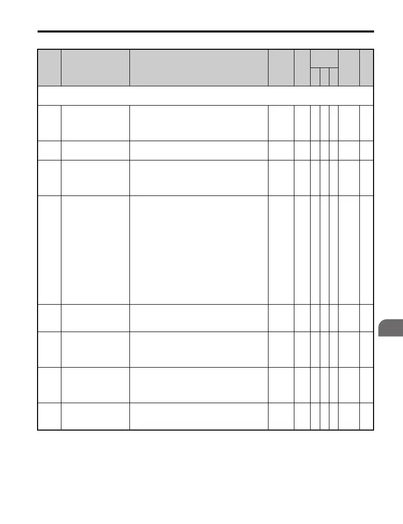
B.2 Parameter Table
YASKAWA TM.V1000.01 V1000 Drive Installation & Start-Up Manual (Preliminary 01-19-07) 337
Parameter List
B
b2: DC Injection Braking
Use b2 parameters to configure DC Injection Braking operation
b2-01
DC Injection Braking
Start Frequency
Sets the frequency at which DC Injection
Braking starts when Ramp to Stop (b1-03 = 0)
is selected. If b2-01< E1-09, DC Injection
Braking starts at E1-09.
0.0 to
10.0
0.5
Hz
AAA 189 —
b2-02
DC Injection Braking
Current
Sets the DC Injection Braking current as a
percentage of the drive rated current.
0 to 75 50% A A − 18A —
b2-03
DC Injection Braking
Time/DC Excitation
Time at Start
Sets the time of DC Injection Braking at start in
units of 0.01 seconds. Disabled when set to 0.00
seconds.
Used to stop a coasting motor.
0.00 to
10.00
0.00
s
<1>
AA− 18B —
b2-04
DC Injection Braking
Time at Stop
Sets the time length of DC Injection Braking at
stop in units of 0.01 seconds.
When b1-03 = 2, actual DC Injection time is
calculated as follows:
(b2-04) x 10 x (Output Freq) / (E1-04).
When b1-03 = 0, this parameter sets the amount
of DC Injection time applied to the motor at the
end of the decel ramp.
This should be set to a minimum of 0.50
seconds when using HSB. This will activate DC
Injection during the final portion of HSB and
help ensure that the motor stops completely.
Disabled when set to 0.00.
0.00 to
10.00
0.50
s
<14>
AA− 18C —
b2-08
Magnetic Flux
Compensation
Capacity
Sets the magnetic flux compensation as a
percentage of the no-load current value
(E2-03).
0 to
1000
0% − A − 190 —
b2-12
Short Circuit Brake
Time at Start
Sets the time for Short-Circuit Brake operation
at start in units of 0.01 seconds. Used when
restarting a coasting motor once it has stopped.
Disabled when set to 0.00.
<32>
0.00 to
25.50
0.00
s
−−A1BA —
b2-13
Short Circuit Brake
Time at Stop
Sets the time for Short-Circuit Brake operation
at stop in units of 0.01 seconds. Used to stop a
motor rotating due to inertia. Disabled when set
to 0.00 seconds.
<32>
0.00 to
25.50
0.50
s
−−A1BB —
b2-15
DC Injection Braking
Current 2
Changes the DC Injection Braking reference
one second after start. Disabled when set to
0.0%.
0 to 100 50% A A − 01BD —
No. Name Description Range Def.
Control
Mode
Addr.
Hex
Pg.
V/f
O
LV
P
M

 Loading...


