B.2 Parameter Table
348 YASKAWA TM.V1000.01 V1000 Drive Installation & Start-Up Manual (Preliminary 01-19-07)
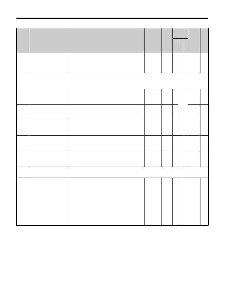
C4-06
Torque Compensation
Primary Delay Time 2
Increase settings when acceleration is
complete, or if an OV fault or error occurs
with sudden changes in the load.
Note: Adjustment is not normally required.
0 to
10000
150
ms
–A–21AH—
C5: Speed Control (ASR)
Use C5 parameters to configure the Automatic Speed Regulator (ASR).
C5 parameters are available only when using V/f control and when Simple PG V/f is enabled (H6-01 = 3).
C5-01
<22>
ASR Proportional
Gain 1 (for Simple
PG V/f Control)
Sets the proportional gain of the speed
control loop (ASR).
0.00 to
300.00
0.20 A
––
21B —
C5-02
<22>
ASR Integral Time 1
(for Simple PG V/f
Control)
Sets the integral time of the speed control
loop (ASR).
0.000 to
10.000
0.200 A 21C —
C5-03
<22>
ASR Proportional
Gain 2 (for Simple
PG V/f Control)
Sets the speed control gain 2 of the speed
control loop (ASR).
Note: Adjustment is not normally required.
0.00 to
300.00
0.02 A −− 21D —
C5-04
<22>
ASR Integral Time 2
(for Simple PG V/f
Control)
Sets the integral time 2 of the speed control
loop (ASR).
Note: Adjustment is not normally required.
0.000 to
10.000
0.050
s
A
––
21E —
C5-05
<22>
ASR Limit (for
Simple PG V/f
Control)
Sets the upper limit for the speed control
loop (ASR) as a percentage of the maximum
output frequency (E1-04).
0.0 to
20.0
5.0% A 21F —
C6: Carrier Frequency
Use C6 parameters to configure the carrier frequency drive settings.
C6-01 Duty Cycle
Selects the load rating for the drive.
0: Heavy Duty (HD)
Applications requiring constant torque (CT).
1: Normal Duty (ND)
Applications requiring derated or variable
torque (VT).
This setting sets the following two drive
characteristics:
Rated output current
Overload tolerance
0,1 1 S S S 223 125
No. Name Description Range Def.
Control
Mode
Addr.
Hex
Pg.
V/
f
O
L
V
P
M

 Loading...


