B.2 Parameter Table
YASKAWA TM.V1000.01 V1000 Drive Installation & Start-Up Manual (Preliminary 01-19-07) 349
Parameter List
B
C6-02
Carrier Frequency
Selection
Selects the number of pulses per second of
the output voltage waveform. Setting range
determined by C6-01 setting.
1: 2.0 kHz
2: 5.0 kHz
3: 8.0 kHz
4: 10.0 kHz
5: 12.5 kHz
6: 15.0 kHz
7: Swing PWM1 (Audible sound 1)
8: Swing PWM2 (Audible sound 2)
9: Swing PWM3 (Audible sound 3)
A: Swing PWM4 (Audible sound 4)
B to E: No setting possible
F: Program (determined by C6-03 through
C6-05)
1 to F
7
<3>
S S S 224 127
C6-03
Carrier Frequency
Upper Limit
Sets the upper and lower limits for the carrier
frequency.
When using Open Loop Vector (OLV) to
control the motor, the carrier frequency
operates at the upper limit (C6-03).
The value for coefficient K is determined by
C6-03.
C6-03 ≥ 10.0 kHz: K = 3
10.0 kHz > C6-03 ≥ 5.0 kHz: K = 2
5.0 kHz > C6-03: K = 1
When C6-05 ≤ 6, C6-04 is disabled (makes
the carrier frequency C6-03 value).
1.0 to
15.0
<8> A A A 225 —
C6-04
Carrier Frequency
Lower Limit
0.4 to
15.0
<8> A - - 226 —
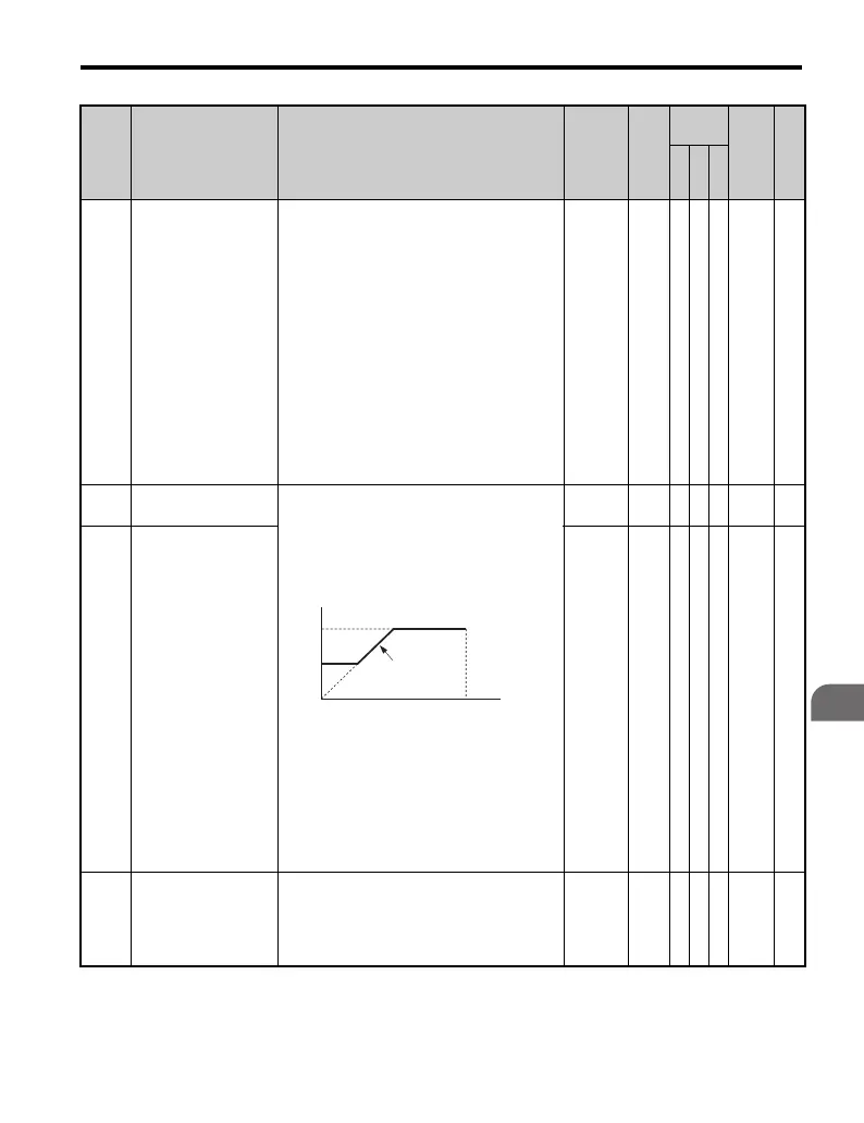
C6-05
Carrier Frequency
Proportional Gain
Sets the relationship of output frequency to
carrier frequency when C6-02 = F.
Note: Carrier frequency is set to C6-03
(upper limit) when operating in Open Loop
Vector Control (OLV) control.
00 to 99
<8> A - - 227 —
No. Name Description Range Def.
Control
Mode
Addr.
Hex
Pg.
V/
f
O
L
V
P
M
carrier frequency
E1-04
max output
frequency
output frequency
× (C6-05) × K
output
frequency
C6-03
C6-04

 Loading...


