B.2 Parameter Table
YASKAWA TM.V1000.01 V1000 Drive Installation & Start-Up Manual (Preliminary 01-19-07) 379
Parameter List
B
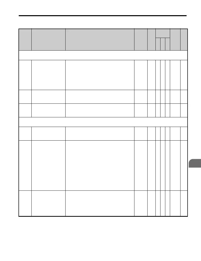
No. Name Description Range Def.
Control
Mode
Addr.
Hex
Pg.
V/
f
O
L
V
P
M
H4: Multi-Function Analog Outputs
Use H4 parameters to configure the multi-function analog output terminals.
H4-01
<40>
Multi-Function
Analog 1 (Terminal
AM Monitor
Selection)
Select the data to be output through multi-
function analog output terminal AM.
Set the desired monitor parameter to the digits
available in U-. For example, enter
“103” for U1-03.
When using this terminal as a through terminal
or when not using it at all, set “000” or “031”.
000 to
999
102 A A A 41D —
H4-02
<22>
Multi-Function
Analog 1 (Terminal
AM Output Gain)
Sets terminal AM output level when selected
monitor is at 100%. Maximum output voltage
is 10 V (can be adjusted with a voltmeter).
-999.9
to
999.9
100.
0%
SSS 41E —
H4-03
<22>
Multi-Function
Analog 1 (Terminal
AM Output Bias)
Sets the voltage level bias for terminal AM.
The bias added is 0 to ±10% with a maximum
voltage output of 10 V as 100%.
-999.9
to
999.9
0.0
%
A A A 41F —
H5: MEMOBUS/Modbus Communications
Use H5 Parameters to connect the drive to a MEMOBUS/Modbus network.
H5-01
<39>
Drive Node Address
Selects drive station node number (address) for
MEMOBUS/Modbus terminals R+, R-, S+, S-.
Cycle power for the setting to take effect.
0 to 20
H
1F A A A 425 —
H5-02
Communication
Speed Selection
Selects the baud rate for MEMOBUS/Modbus
terminals R+, R-, S+ and S-. Cycle power for
the setting to take effect.
0: 1200 bps
1: 2400 bps
2: 4800 bps
3: 9600 bps
4: 19200 bps
5: 38400 bps
6: 57600 bps
7: 76800 bps
8: 115200 bps
0 to 8 3 A A A 426 —
H5-03
Communication
Parity Selection
Selects the communication parity for
MEMOBUS/Modbus terminals R+, R-, S+ and
S-. Cycle power for the setting to take effect.
0: No parity
1: Even parity
2: Odd parity
0 to 2 0 A A A 427 —

 Loading...


