B.2 Parameter Table
378 YASKAWA TM.V1000.01 V1000 Drive Installation & Start-Up Manual (Preliminary 01-19-07)
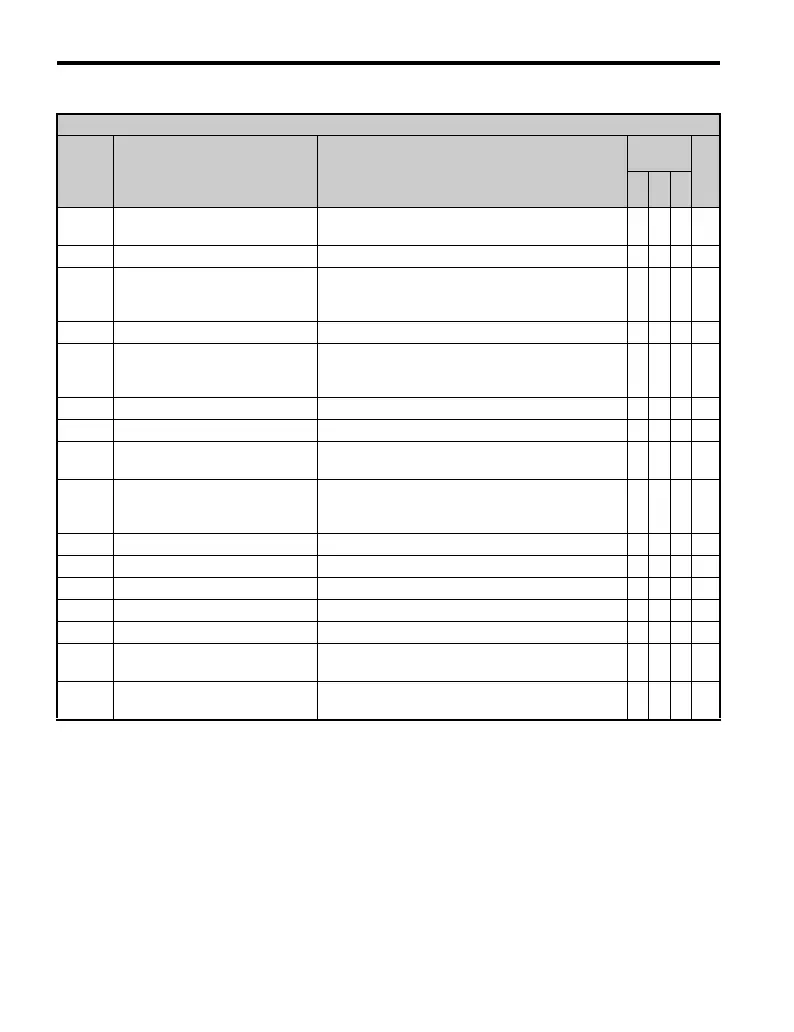
H3 Multi-Function Analog Input Settings
H3-
Setting
Function Maximum Input Level Possible
Control
Mode
Pg.
V/
f
O
LV
P
M
0 Frequency Bias (A1)
Max output frequency (E1-04).
Same value can be set using H3-02 and H3-10.
OOO—
1 Frequency Gain Frequency reference (voltage). O O O —
2
Auxiliary Frequency Reference
(used as a second frequency
reference)
Max output frequency (E1-04).
Same value can be set using H3-02 and H3-10.
OOO—
4 Output Voltage Bias Motor rated voltage (E1-05). O – O —
7
Overtorque/Undertorque
Detection Level
Motor rated torque for Open Loop Vector (OLV)
control.
Drive rated current (when using V/f control).
OOO—
B PID Feedback Max output frequency (E1-04). O O O —
C PID Set Point Max output frequency (E1-04). O O O —
E Motor Temperature (PTC input)
10 V = 100.00%
Determined by L1-03 and L1-04.
OOO—
F
Not used (use this setting if the
terminal is not used or is used as a
pass-through terminal)
– OOO—
10 FWD Torque Limit Motor rated torque. − O − —
11 REV Torque Limit Motor rated torque. − O − —
12 Regenerative Torque Limit Motor rated torque. − O − —
15 FWD/REV Torque Limit Motor rated torque. − O − —
16 Differential PID Feedback 10 V = 100% O O O —
30
DriveWorksEZ
Analog Input 1
– OOO—
31
DriveWorksEZ
Analog Input 2
– OOO—

 Loading...


