B .2 P a ra m e te r Ta b le
YASKAWA TM.V1000.01 V1000 Drive Installation & Start-Up Manual (Preliminary 01-19-07) 373
Parameter List
B
7B KEB Ride-Thru 2 (N.O.)
Closed: KEB deceleration at momentary power loss
command 2 (N.O. contact)
OOO—
7C Short-Circuit Braking (N.O.) Enabled only when using PM Open Loop Vector (PM).
Open: Normal operation
Closed: Short-Circuit Braking
--O—
7D Short-Circuit Braking (N.C.) - - O —
7E
Forward/Reverse Detection
(for Simple V/f w/PG)
Direction of rotation detection (for Simple V/f w/PG) O - - —
No. Name Description Range Def.
Control
Mode
Addr.
Hex
Pg.
V/
f
O
L
V
P
M
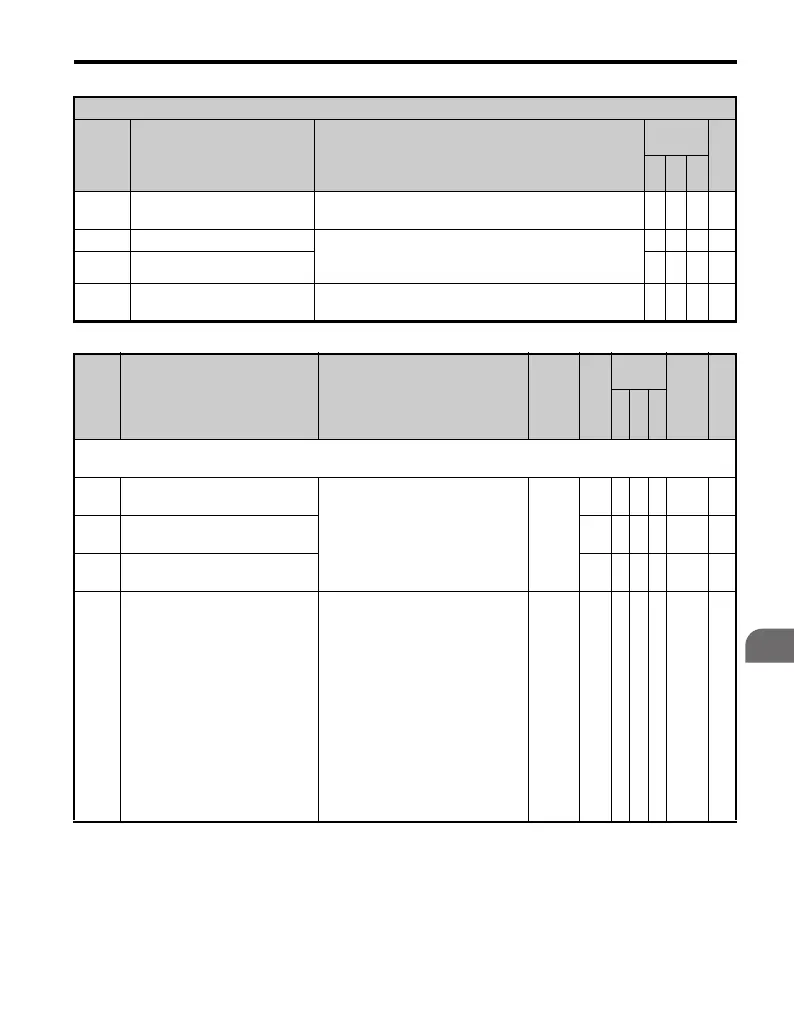
H2: Multi-Function Digital Outputs
Use H2 parameters to assign functions to the multi-function digital outputs.
H2-01
Terminal MA, MB and MC
Function Selection (relay)
Refer to “Multi-Function Digital
Output Selection Table” for a
description of setting values.
0 to 192
EAAA40B—
H2-02
Terminal P1 Function Selection
(open-collector)
0AAA40C—
H2-03
Terminal P2 Function Selection
(open-collector)
2AAA40D—
H2-06 Watt Hour Output Unit Selection
Sets the display units for one of the
multi-function output terminals that
is assigned to output the watt hours
(H2- = 39) is the value every
200 ms. An output pulse of 200 ms
is provided for every kWh that
occurs. Intended to drive a counter,
meter or PLC for logging kWh.
0: 0.1 kWh units
1: 1 kWh units
2: 10 kWh units
3: 100 kWh units
4: 1000 kWh units
0 to 4 0 A A A 437 —
H1 Multi-Function Digital Input Selections
H1-
Setting
Function Description
Control
Mode
Pg.
V/
f
O
LV
P
M

 Loading...


