3.2 Standard Connection Diagram
YASKAWA TM.V1000.01 V1000 Drive Installation & Start-Up Manual (Preliminary 01-19-07) 57
Electrical Installation
3
Figure 3.1
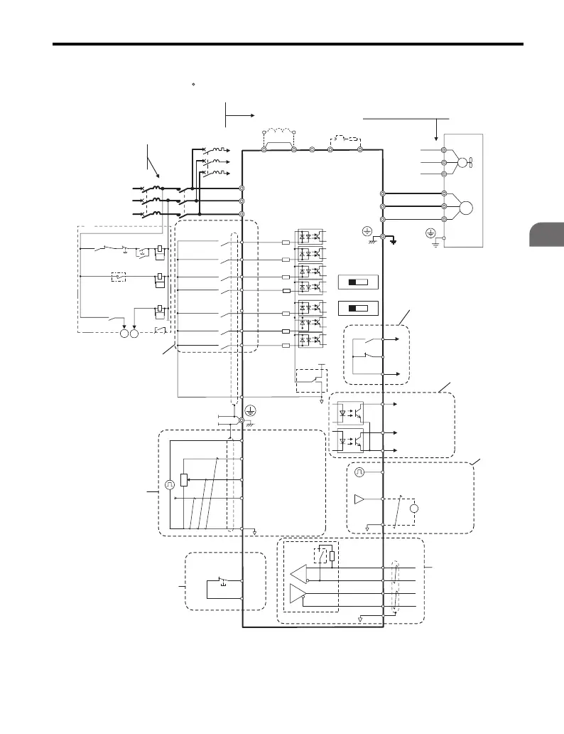
Figure 3.1 Drive Standard Connection Diagram
SA
Motor
Cooling fan
Forward run/stop
Reverse run/stop
External fault
Fault reset
Multi-step
speed 2
Jog reference
0 to +10 Vdc
(2 mA)
DIP
switch S3
DC reactor
(option)
Digital inputs
(default setting)
Comm.
connector
Hardwire
Baseblock
command
input
Hardwire
Baseblock
stop switch
Fault
Drive
Shield ground
terminal
Thermal relay
(option)
Braking resistor
(option)
Main circuit
Control circuit
Thermal relay for
motor cooling fan
Fault relay
Shielded lines are circled with a dashed line, while twisted-pair, shielded cables have an additional cross line.
A double circle O indicates a main circuit terminal, while a single circle O indicates a control terminal.
All analog and digital I/O are programmable for multiple functions.
Additional Notes:
1 MCCB
MC
2 MCCB
r1
s1
t1
R/L1
S/L2
T/L3
S1
S2
S3
S4
S5
S6
S7
*3
*
1
*
2
-
B1+1+2 B2
*
4
R/L1
S/L2
T/L3
MC
THRX
TRX
MC
TRX
MC MA
U/T1
V/T2
W/T3
24
V
0
V
MA
P1
MB
MC
VI
OFF ON
+
24
V 8
mA
*
5
M
M
r1
s1
t1
FU
FV
FW
U
V
W
SC
P2
MP
AM
AC
PC
IG
R
+
R
-
S
+
S
-
+
-
AM
HC
H1
RP
+V
A1
A2
AC
2 k
W
*
6
Pulse train input
(max. 32 kHz)
Ground
10 Ω or less (400 V class)
100 Ω or less (200 V class)
0 to +10 V (20 kΩ) or
-10 to +10 V
Setting power supply
+10.5 max. 20 mA
0 to +10 V (20 kΩ) or
-10 to +10 V
4 to 20 mA (250 Ω)
-10 to +10 V
For single phase 200 V
power supply, use
R/L1 and S/L2.
Confirm blower motor voltage
is equal to drive input voltage
before connecting.
During Run
(photocoupler 1)
Frequency agree
(photocoupler 2)
Photocoupler
output common
Digital output
48 Vdc, 50 mA or less
(default setting)
Pulse train output
0 to 32 kHz
Analog monitor
output
Digital output
250 Vac, 10 mA to 1 A
30 Vdc, 10 mA to 1 A
(default setting)
MEMOBUS/
Modbus comm.
RS-485/422
Main speed
frequency
reference.
Multi-function
programmable
Multi-step
speed 1
main/aux switch
2 MCCB
THRX
OFF
ON
MC
SA
SA
three phase
power supply
200 to 240 V
Jumper
DIP switch S1
DIP switch S2
Sink
Source
Termination
resistor
120 Ω, 1/2 W
Terminals +1, +2, , B1, and B2
are for connecting options.
Never connect power supply
lines to these terminals.
_
Monitor
output
CIMR-VU

 Loading...


