3.7 Control Circuit Wiring
78 YASKAWA TM.V1000.01 V1000 Drive Installation & Start-Up Manual (Preliminary 01-19-07)
■ Output Terminals
Table 3.7 Control Circuit Output Terminals
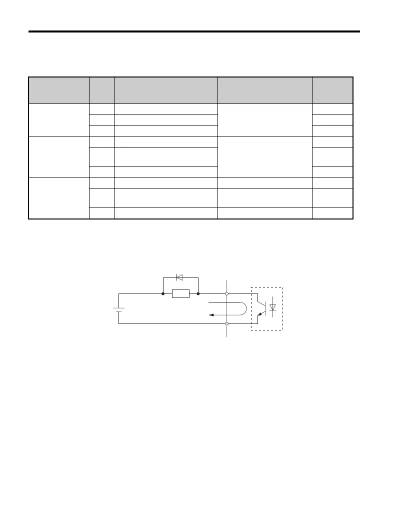
Connect a suppression diode as shown in Figure 3.19 when driving a reactive load
such as a relay coil. Make sure the diode rating is greater than the circuit voltage.
Figure 3. 19
Figure 3.19 Connecting a Suppression Diode
Type No. Terminal Name (Signal)
Function (Signal Level)
Default Setting
Reference
Multi-Function
Digital Output
MA N.O. (fault)
Digital output
30 Vdc, 10 mA to 1 A
250 Vac, 10 mA to 1 A
—
MB N.C. output (fault) —
MC Digital output common —
Multi-Function
Photocoupler
Output
P1 Photocoupler output 1 (during run)
Photocoupler output
48 Vdc, 50 mA (or less)
—
P2
Photocoupler output 2
(Frequency agree)
—
PC Photocoupler output common —
Monitor Output
MP Pulse train output 32 kHz (max) —
AM Analog monitor output
DC 0 to 10 V (2 mA or less)
Resolution: 1/1000
—
AC Monitor common 0 V —
A – External power supply,
maximum 48 V
C–Coil
B – Suppression diode D – 50 mA or less
B
C
D

 Loading...


