3.7 Control Circuit Wiring
YASKAWA TM.V1000.01 V1000 Drive Installation & Start-Up Manual (Preliminary 01-19-07) 77
Electrical Installation
3
■ Input Terminals
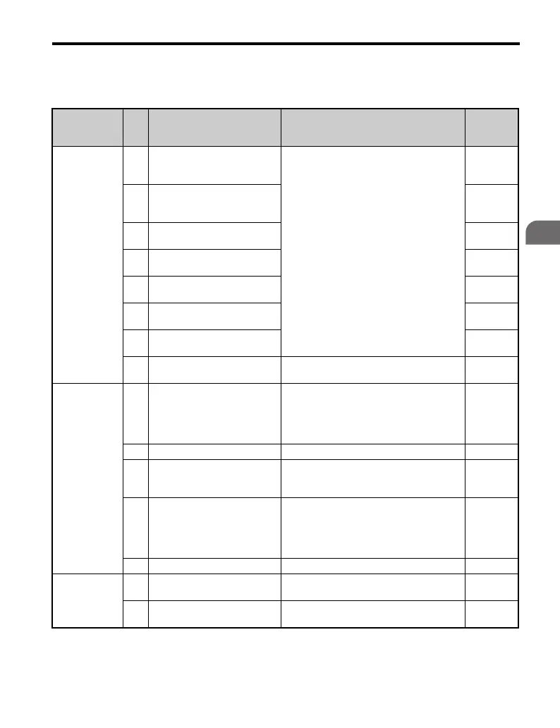
Table 3.6 Control Circuit Input Terminals
Type No. Terminal Name (Signal)
Function (Signal Level)
Default Setting
Reference
Multi-
Function
Digital Inputs
S1
Multi-function input 1
(Closed: Forward run,
Open: Stop)
Photocoupler
DC24 V, 8 mA
Note: Drive preset to sinking mode. When
using source mode, set DIP switch S3 to
allow for a 24 Vdc (±10%) external power
supply. Refer to page 84.
—
S2
Multi-function input 2
(Closed: Reverse run,
Open: Stop)
—
S3
Multi-function input 3
(External fault (N.O.))
—
S4
Multi-function input 4
(Fault reset)
—
S5
Multi-function input 5
(Multi-step speed reference 1)
—
S6
Multi-function input 6
(Multi-step speed reference 2)
—
S7
Multi-function input 7
(Jog reference)
—
SC
Multi-function input common
(Control common)
Sequence common —
Main
Frequency
Reference
Input
RP
Multi-function pulse train input
(frequency reference)
Response frequency: 0.5 to 32 kHz
(Duty Cycle: 30 to 70%)
(High level voltage: 3.5 to 13.2 V)
(Low level voltage: 0.0 to 0.8 V)
(input impedance: 3 kΩ)
—
+V Analog input power supply +10.5 V (max allowable current 20 mA) —
A1
Multi-function analog input 1
(frequency reference)
Input voltage
DC 0 to +10 V (20 kΩ) resolution: 1/1000
DC -10 to +10 V (20 kΩ) resolution: 1/500
—
A2 Multi-function analog input 2
Input voltage or input current
DC 0 to +10 V (20 kΩ) resolution: 1/1000
DC -10 to +10 V (20 kΩ) resolution: 1/500
4 to 20 mA or 0 to 20 mA (250 Ω)
resolution: 1/500
—
AC Frequency reference common 0 V —
Hardwire
Baseblock
HC
Power supply for hardwire
baseblock command
+24 V (max 10 mA allowed) —
H1 Hardwire baseblock command
Open: Hardwire baseblock
Closed: Normal operation
—

 Loading...


