7.4 Installing Peripheral Devices
YASKAWA TM.V1000.01 V1000 Drive Installation & Start-Up Manual (Preliminary 01-19-07) 297
Peripheral Devices &
Options
7
• To suppress harmonic current or improve the power factor of the power supply.
• When using an advancing capacitor switch.
• With a large capacity power supply transformer (over 600 kVA).
Note: Use an AC or DC reactor when also connecting a thyristor converter (such as a DC
drive) to the same power supply system, regardless of the conditions of the power
supply.
■
Connecting an AC Reactor
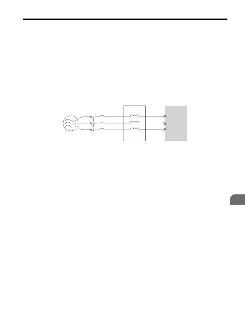
Figure 7.2
Figure 7.2 Connecting an AC Reactor
■
Connecting a DC Reactor
Ensure the jumper between terminals +1 and +2 (terminals are jumpered for
shipment) is removed when connecting a DC reactor. The jumper must be installed
if no DC reactor is used. Refer to Figure 7.3 for an example of DC reactor wiring.
A – Power supply C – AC reactor
B – MCCB D – Drive
BA
CD
R/L1 U
V
W
X
Y
Z
S/L2
T/L3

 Loading...


