3.5 Protective Covers
YASKAWA TM.V1000.01 V1000 Drive Installation & Start-Up Manual (Preliminary 01-19-07) 67
Electrical Installation
3
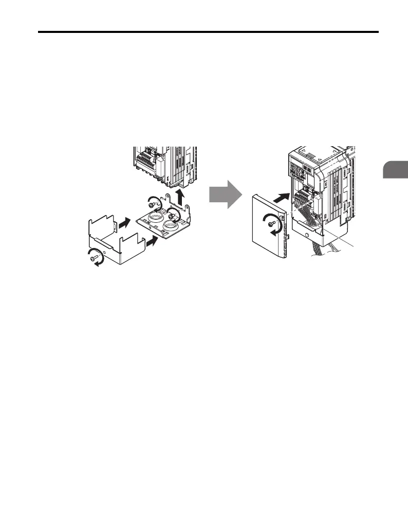
■ Reattaching the Protective Covers
Pass power wiring and control signal wiring through the exit holes on the bottom of
the conduit bracket of the drive. Place power wiring and control signal wiring in
separate conduits. Connect all wiring and ensure that all connections are correct
after installing the drive and connecting other devices. Reattach all protective
covers when wiring is complete.
Figure 3.14
Figure 3.14 Reattach the Protective Covers and
Conduit Bracket on an IP20/NEMA Type 1 Drive
A – Power wiring and control signal wiring should
pass out through different exit holes at the
bottom of the drive.

 Loading...


