B.2 Parameter Table
422 YASKAWA TM.V1000.01 V1000 Drive Installation & Start-Up Manual (Preliminary 01-19-07)
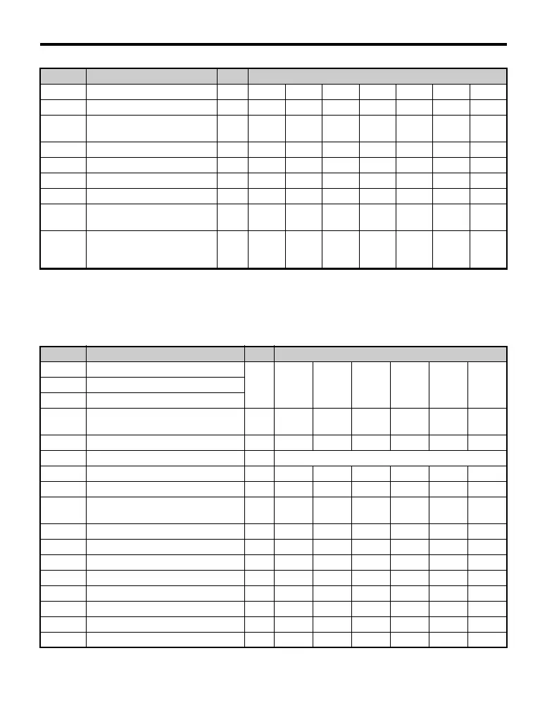
■ Three-Phase 200 V Class Models
CIMR-V2A0001 to CIMR-V2A0012
Table B.2 Default Settings Determined by Drive Capacity (o2-04):
Three-Phase 200 V Class Models CIMR-V2A0001 to CIMR-V2A0012
L2-03 Minimum Baseblock Time s 0.2 0.2 0.2 0.3 0.4 0.5 0.6
L2-04 Voltage Restoration Time s 0.3 0.3 0.3 0.3 0.3 0.3 0.3
L3-24
Inertia Calculations for Motor
Acceleration Time
s 0.177 0.151 0.178 0.142 0.166 0.145 0.154
L8-02 OH Pre-Alarm Level °C 90 90 90 100 100 100 100
L8-04 OH Detection Level °C 100 100 100 110 110 110 110
L8-09 Ground Protection Selection – 0 0 0 0 0 0 0
L2-05 UV Detection Level C 160 160 160 160 160 160 160
C6-21
Two Phase/Three Phase
Switching Voltage Level (%)
%30303030303030
C6-22
Two Phase/Three Phase
Switching Frequency Level
(Hz)
Hz 18 18 18 18 18 18 18
No. Name Units Factory Default Value
– Drive Capacity
kW 0.1 0.2 0.4 0.75 1.5 2.2E2-11 Motor Rated Capacity
E4-11 Motor Rated Capacity for Motor 2
o2-04 Drive Capacity Selection –
96
(60H)
97
(61H)
98
(62H)
99
(63H)
100
(64H)
101
(65H)
b3-04 V/f during Speed Search % 100 100 100 100 100 100
b8-03 Energy Control Carrier Time Constant s 0.50 (Open Loop Vector Control)
b8-04 Energy Saving Coefficient – 0 0 288.2 223.7 169.4 156.8
C6-02 Carrier Frequency Selection kHz 10 10 10 10 8 8
–
Carrier Frequency Selection Upper
Limit
kHz151515151515
E2-01 Motor Rated Current A 0.6 1.1 1.9 3.3 6.2 8.5
E2-02 Motor Rated Slip Hz 2.5 2.6 2.9 2.5 2.6 2.9
E2-03 Motor No-Load Current A 0.4 0.8 1.2 1.8 2.8 3
E2-05 Motor Resistance Between Lines Ω 35.98 20.56 9.842 5.156 1.997 1.601
E2-06 Motor Leakage Inductance % 21.6 20.1 18.2 13.8 18.5 18.4
E4-01 Motor 2 Rated Current A 0.6 1.1 1.9 3.3 6.2 8.5
E4-02 Motor 2 Rated Slip Hz 2.5 2.6 2.9 2.5 2.6 2.9
E4-03 Motor 2 No-Load Current A 0.4 0.8 1.2 1.8 2.8 3
No. Name Units Factory Default Value

 Loading...


