B.2 Parameter Table
YASKAWA TM.V1000.01 V1000 Drive Installation & Start-Up Manual (Preliminary 01-19-07) 423
Parameter List
B
■ Three-Phase 200 V Class Model CIMR-V2A0020
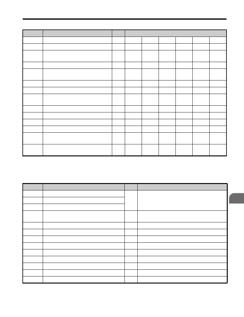
Table B.3 Default Settings Determined by Drive Capacity (o2-04):
Three-Phase 200 V Class Model CIMR-V2A0020
E4-05 Motor 2 Line-to-Line Resistance Ω 35.98 20.56 9.842 5.156 1.997 1.601
E4-06 Motor 2 Leakage Inductance % 21.6 20.1 18.2 13.8 18.5 18.4
E2-10
Torque Compensation Motor Iron
Loss
W 6 11 14 26 53 77
n1-03 Hunting Prevention Time Constant ms 10 10 10 10 10 10
L2-02
Momentary Power Loss Ride-Thru
Time
s 0.1 0.1 0.1 0.2 0.3 0.5
L2-03 Minimum Baseblock Time s 0.2 0.2 0.2 0.3 0.4 0.5
L2-04 Voltage Restoration Time s 0.3 0.3 0.3 0.3 0.3 0.3
L3-24
Motor Accel Time for Inertia
Calculations
s 0.177 0.151 0.178 0.142 0.166 0.145
L8-02 OH Pre-Alarm Level °C90909090100100
L8-04 OH Detection Level °C 100 100 100 100 110 110
L8-09 Ground Protection Selection – 0 0 0 0 0 0
L2-05 UV Detection Level C 190 190 190 190 190 190
C6-21
Two Phase/Three Phase Switching
Voltage Level (%)
%303030303030
C6-22
Two Phase/Three Phase Switching
Frequency Level (Hz)
Hz 18 18 18 18 18 18
No. Name Units Factory Default Value
– Drive Capacity
kW 3.7E2-11 Motor Rated Capacity
E4-11 Motor Rated Capacity for Motor 2
o2-04 Drive Capacity Selection –
103
(67H)
b3-04 V/f during Speed Search % 100
b8-03 Energy Control Carrier Time Constant s
b8-04 Energy Saving Coefficient – 122.9
C6-02 Carrier Frequency Selection kHz 8
– Carrier Frequency Selection Upper Limit kHz 15
E2-01 Motor Rated Current A 14
E2-02 Motor Rated Slip Hz 2.73
E2-03 Motor No-Load Current A 4.5
E2-05 Motor Resistance Between Lines Ω 0.771
No. Name Units Factory Default Value

 Loading...


