B.2 Parameter Table
424 YASKAWA TM.V1000.01 V1000 Drive Installation & Start-Up Manual (Preliminary 01-19-07)
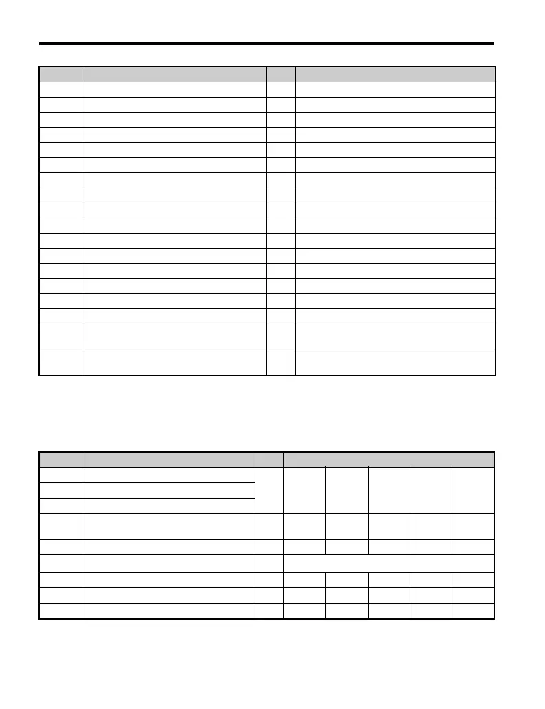
■ Three-Phase 400V Class Models
CIMR-V4A0001 to CIMR-V4A0007
Table B.4 Default Settings Determined by Drive Capacity (o2-04):
Three-Phase, 400 V Class Models CIMR-V4A0001 to CIMR-V4A0007
E2-06 Motor Leakage Inductance % 19.6
E4-01 Motor 2 Rated Current A 14
E4-02 Motor 2 Rated Slip Hz 2.73
E4-03 Motor 2 No-Load Current A 4.5
E4-05 Motor 2 Line-to-Line Resistance Ω 0.771
E4-06 Motor 2 Leakage Inductance % 19.6
E2-10 Torque Compensation Motor Iron Loss W 112
n1-03 Hunting Prevention Time Constant ms 10
L2-02 Momentary Power Loss Ride-Thru Time s 1
L2-03 Minimum Baseblock Time s 0.6
L2-04 Voltage Restoration Time s 0.3
L3-24 Inertia Motor Acceleration Time s 0.154
L8-02 OH Pre-Alarm Level °C100
L8-04 OH Detection Level °C110
L8-09 Ground Protection Selection – 0
L2-05 UV Detection Level C 190
C6-21
Two Phase/Three Phase Switching Voltage
Level (%)
%30
C6-22
Two Phase/Three Phase Switching Frequency
Level (Hz)
Hz 18
No. Name Units Factory Default Value
– Drive Capacity
kW 40P2 40P4 40P7 41P5 42P2E2-11 Motor Rated Capacity
E4-11 Motor Rated Capacity for Motor 2
o2-04 Drive Capacity Selection –
145
(91H)
146
(92H)
147
(93H)
148
(94H)
149
(95H)
b3-04 V/f during Speed Search % 100 100 100 100 100
b8-03 Energy Control Carrier Time Constant sec.
b8-04 Energy Saving Coefficient – 713.8 576.4 447.4 338.8 313.6
C6-02 Carrier Frequency Selection kHz 8 8 8 8 8
– Carrier Frequency Selection Upper Limit kHz 15 15 15 15 15
No. Name Units Factory Default Value

 Loading...


