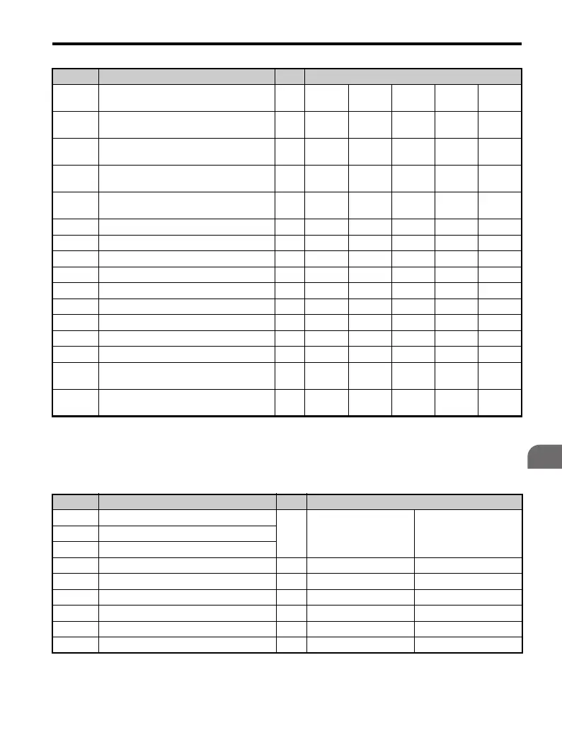
B.2 Parameter Table
YASKAWA TM.V1000.01 V1000 Drive Installation & Start-Up Manual (Preliminary 01-19-07) 425
Parameter List
B
■ Three-Phase 400 V Class Models
CIMR-V4A0009 to CIMR-V4A0011
Table B.5 Default Settings Determined by Drive Capacity (o2-04):
Three-Phase 400 V Class Models CIMR-V4A0009 to CIMR-V4A0011
E2-01
(E4-01)
Motor Rated Current A 0.6 1 1.6 3.1 4.2
E2-02
(E4-02)
Motor Rated Slip Hz 2.5 2.9 2.6 2.5 3
E2-03
(E4-03)
Motor No-Load Current A 0.4 0.6 0.8 1.4 1.5
E2-05
(E4-05)
Motor Resistance Between Lines Ω 83.94 38.198 22.459 10.1 6.495
E2-06
(E4-06)
Motor Leakage Inductance % 21.9 18.2 14.3 18.3 18.7
E2-10Torque Compensation Motor Loss W1214265377
L2-02 Momentary Power Loss Ride-Thru Time sec. 0.1 0.1 0.2 0.3 0.5
L2-03 Minimum Baseblock Time sec. 0.2 0.2 0.3 0.4 0.5
L2-04 Voltage Restoration Time sec. 0.3 0.3 0.3 0.3 0.3
L3-24 Inertia Motor Acceleration Time sec. 0.151 0.178 0.142 0.166 0.145
L8-02 OH Pre-Alarm Level °C 100 100 100 100 100
L8-04 OH Detection Level °C 110 110 110 110 110
L8-09 Ground Protection Selection – 0 0 0 0 0
L2-05 UV Detection Level C 380 380 380 380 380
C6-21
Two Phase/Three Phase Switching Voltage
Level (%)
%3030303030
C6-22
Two Phase/Three Phase Switching
Frequency Level (Hz)
Hz 18 18 18 18 18
No. Name Units Factory Default Value
– Drive Capacity
kW 43P0 43P7E2-11 Motor Rated Capacity
E4-11 Motor Rated Capacity for Motor 2
o2-04 Drive Capacity Selection – 150 (96H) 151 (97H)
b3-04 V/f during Speed Search % 100
b3-06 Output Current 1 during Speed Search – 0.5
b8-04 Energy Saving Coefficient – 245.8
C6-02 Carrier Frequency Selection kHz 8
– Carrier Frequency Selection Upper Limit kHz 15
No. Name Units Factory Default Value

 Loading...


