B.2 Parameter Table
YASKAWA TM.V1000.01 V1000 Drive Installation & Start-Up Manual (Preliminary 01-19-07) 409
Parameter List
B
U1-07 DC Bus Voltage Displays the voltage in the DC bus.
10 V: 400 V
(800 V)
1 V A A A 46
U1-08 Output Power
Displays the output voltage (this value is
determined internally).
10 V:
Drive
capacity
(kW)
(max. motor
capacity
allowed)
<27
>
AAA 47
U1-09 Torque Reference
Monitor of internal torque reference value for
Open Loop Vector (OLV) control
0.1% – – A –
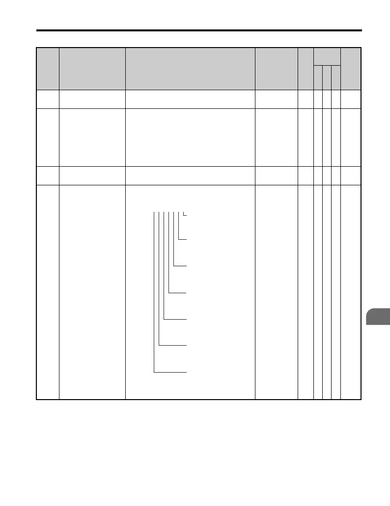
U1-10 Input Terminal Status
Verifies that the input terminal is on or off.
No output
signal
available
–AAA49
No. Name Description Range Def.
Control
Mode
Addr.
Hex
V/
f
O
L
V
P
M
U1-09
=
0000000
1: FWD run
command
(terminal S1
enabled)
1: REV run
command
(terminal S2
enabled)
1: Multi-Function
Digital
Input 1 (terminal
S3 enabled)
1: Multi-Function
Digital
Input 2 (terminal
S4 enabled)
1: Multi-Function
Digital
Input 3 (terminal
S5 enabled)
1: Multi-Function
Digital
Input 4 (terminal
S6 enabled)
1: Multi-Function
Digital
Input 5 (terminal
S7 enabled)

 Loading...


