B.2 Parameter Table
410 YASKAWA TM.V1000.01 V1000 Drive Installation & Start-Up Manual (Preliminary 01-19-07)
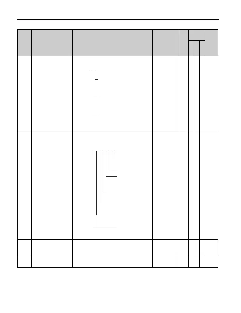
U1-11
Output Terminal
Status
Verifies that the output terminal is on or off.
No output
signal
available
–AAA4A
U1-12
Drive
Status
Verifies the drive operation status.
No output
signal
available
–AAA4B
U1-13
Terminal A1 Input
Vo l t a g e
Displays the frequency reference (voltage)
input to terminal A2.
Displays 100% when the input is 10 V
10 V: 100%
0.1
%
AAA 4E
U1-14
Terminal A2 Input
Vo l t a g e
Displays the voltage input to terminal A2.
Displays 100% when the input is 10 V.
10 V: 100%
0.1
%
AAA 4F
No. Name Description Range Def.
Control
Mode
Addr.
Hex
V/
f
O
L
V
P
M
U1-10
=
000
1: Multi-Function
Digital Output 1
(terminal P1) enabled
1: Multi-Function
Digital Output 2
(terminal P2) enabled
1: Multi-Function
Digital Output (fault)
(terminal MA/MB-MC)
U1-11
=
00000000
1: During run
1: During
zero-speed
1: During REV
1: During fault
reset
signal input
1: During speed
agree
1: Drive ready
1: During alarm
detection
1: During fault
detection

 Loading...


