4.4 Basic Parameter Adjustments
152 YASKAWA TM.V1000.01 V1000 Drive Installation & Start-Up Manual (Preliminary 01-19-07)
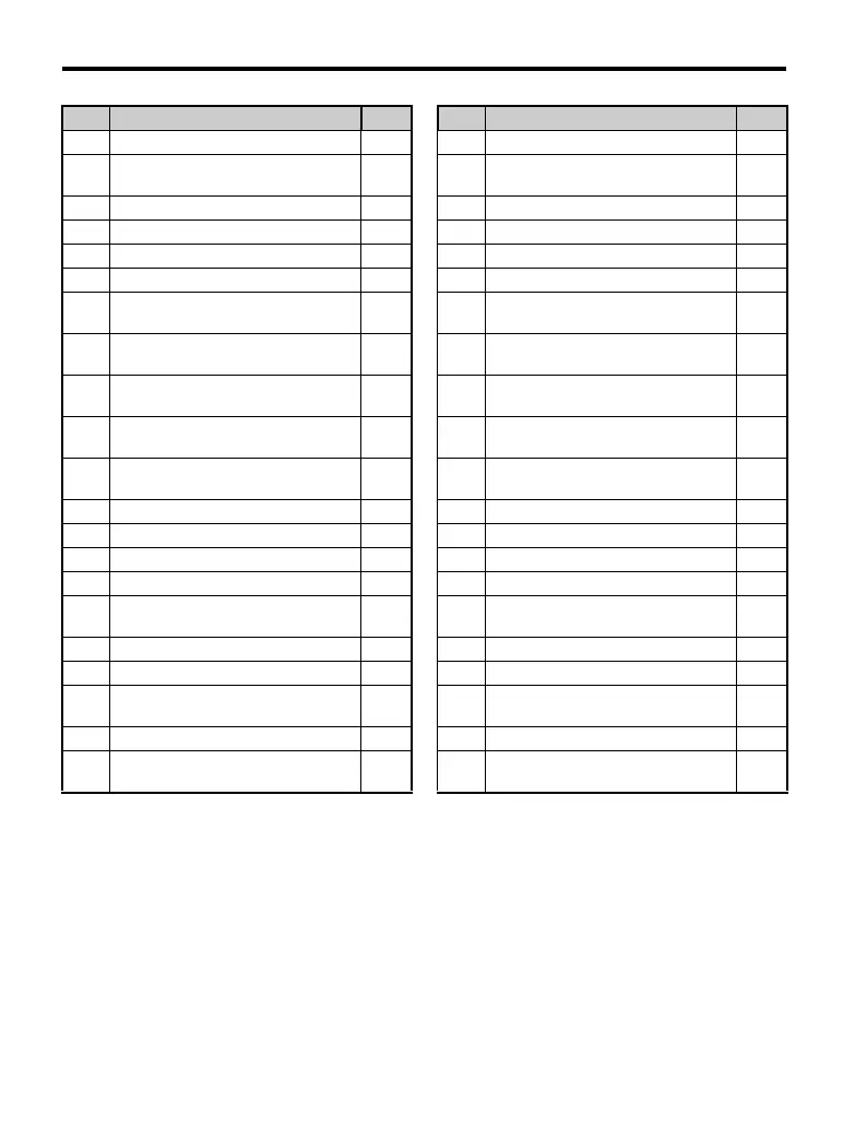
U2-06 Motor Speed at Previous Fault 412 U4-21 Run Command Selection Results 417
U2-07 Output Voltage at Previous Fault 412 U4-22
MEMOBUS/Modbus Communications
Reference
417
U2-08 DC Bus Voltage at Previous Fault 412 U4-23 Option Card Reference 418
U2-09 Output Power at Previous Fault 412 U5-01 PID Feedback 418
U2-10 Torque Reference at Previous Fault 412 U5-02 PID Input (feedback) 418
U2-11 Input Terminal Status at Previous Fault 412 U5-03 PID Output 418
U2-12
Output Terminal Status at Previous
Fault
412 U5-04 PID Setpoint 418
U2-13
Drive Operation Status at Previous
Fault
413 U6-01 Torque Reference (Internal) 418
U2-14
Cumulative Operation Time at
Previous Fault
413 U6-02 Motor Secondary Current (Iq) 418
U2-15
Soft Starter Speed Reference at
Previous Fault
413 U6-03 Motor Excitation Current (ld) 418
U2-16 Motor q-Axis Current at Previous Fault 413 U6-04
Output of speed control (ASR)
(for Simple V/f PG)
418
U2-17 Motor d-Axis Current at Previous Fault 413 U6-05 Output voltage reference (Vq) 418
U3-01 Most Recent Fault 413 U6-06 Output Voltage Reference (Vd) 418
U3-02 2nd Most Recent Fault 413 U6-07 q-axis ACR Output 418
U3-03 3rd Most Recent Fault 413 U6-08 d-Axis ACR Output 418
U3-04 4th Most Recent Fault 413 U6-17
Energy Savings Coefficient
Calculation Value
419
U3-05 5th Most Recent Fault 413 U6-18 PID Differential Feedback 419
U3-06 6th Most Recent Fault 413 U6-19 PID Adjusted Feedback 419
U3-07 7th Most Recent Fault 413 U6-20
Frequency Reference Bias
(Up/Down 2)
419
U3-08 8th Most Recent Fault 413 U6-21 Offset Frequency 419
U3-09 9th Most Recent Fault 414
U8-
Custom Monitors for DriveWorks EZ
419
No. Parameter Name Page No. Parameter Name Page

 Loading...


