4.4 Basic Parameter Adjustments
YASKAWA TM.V1000.01 V1000 Drive Installation & Start-Up Manual (Preliminary 01-19-07) 151
Start-Up Programming &
Operation
4
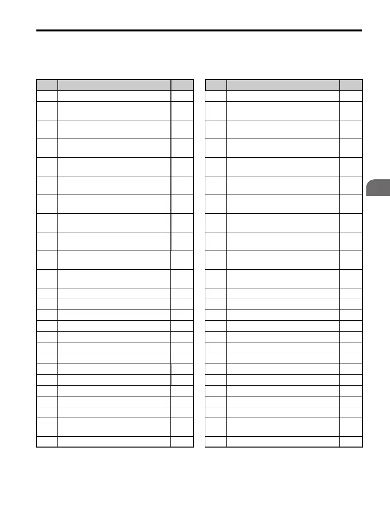
Refer to Parameter List on page 331 for more details about Drive Status Monitors.
Table 4.6 Drive Status Monitors
No. Parameter Name Page No. Parameter Name Page
U1-01 Frequency Reference 408 U3-10 10th Most Recent Fault 414
U1-02 Output Frequency 408 U3-11
Cumulative Operation Time at Most
Recent Fault
414
U1-03 Output Current 408 U3-12
Cumulative Operation Time at 2nd
Most Recent Fault
414
U1-04 Control Mode 408 U3-13
Cumulative Operation Time at 3rd
Most Recent Fault
414
U1-05 Motor Speed 408 U3-14
Cumulative Operation Time at 4th
Most Recent Fault
414
U1-06 Output Voltage Reference 408 U3-15
Cumulative Operation Time at 5th
Most Recent Fault
414
U1-07 DC Bus Voltage 409 U3-16
Cumulative Operation Time at 6th
Most Recent Fault
414
U1-08 Output Power 409 U3-17
Cumulative Operation Time at 7th
Most Recent Fault
414
U1-09 Torque Reference 409 U3-18
Cumulative Operation Time at 8th
Most Recent Fault
414
U1-10 Input Terminal Status 409 U3-19
Cumulative Operation Time at 9th
Most Recent Fault
414
U1-11 Output Terminal Status 410 U3-20
Cumulative Operation Time at 10th
Most Recent Fault
414
U1-12 Drive Status 410 U4-01 Accumulated Operation Time 415
U1-13 Terminal A1 Input Voltage 410 U4-02 Number of Run Commands 415
U1-14 Terminal A2 Input Voltage 410 U4-03 Cooling Fan Operation Time 415
U1-16 Output Frequency after SoftStart 411 U4-05 Capacitor Maintenance 415
U1-18 oPE Fault 411 U4-07 IGBT Maintenance 415
U1-19 MEMOBUS/Modbus Error Code 411 U4-09 LED Check 415
U1-24 Input Pulse Monitor 411 U4-10 kWH, Lower 4 Digits 416
U1-25 Software Number (Flash) 411 U4-11 kWH, Upper 5 Digits 416
U1-26 Software Number (ROM) 411 U4-13 Peak Hold Current 416
U2-01 Current Fault 411 U4-14 Peak Hold Output Frequency 416
U2-02 Previous Fault 411 U4-16 Motor Overload Estimate (OL1) 416
U2-03 Frequency Reference at Previous Fault 412 U4-18 Frequency Reference Selection Results 416
U2-04 Output Frequency at Previous Fault 412 U4-19
Frequency Reference from
MEMOBUS/Modbus Communications
417
U2-05 Output Current at Previous Fault 412 U4-20 Option Frequency Reference 417

 Loading...


