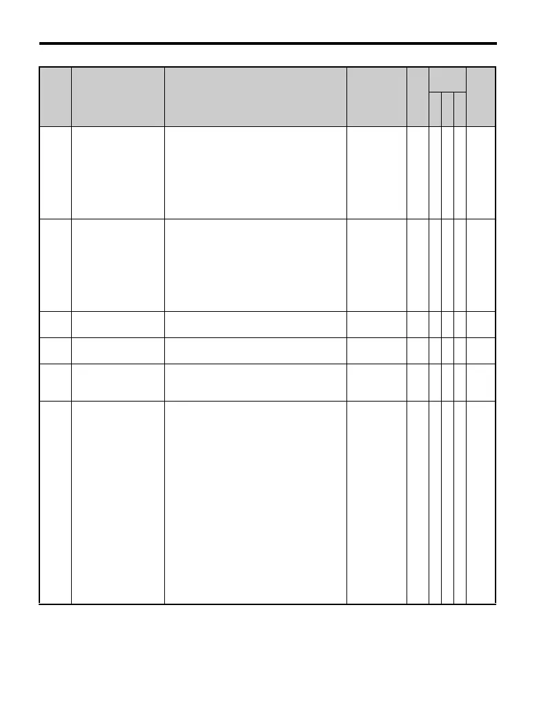
B.2 Parameter Table
416 YASKAWA TM.V1000.01 V1000 Drive Installation & Start-Up Manual (Preliminary 01-19-07)
U4-10 kWH, Lower 4 Digits
Monitors the drive output power. The value is
shown as a 9 digit number displayed across
two monitor parameters, U4-10 and U4-11.
Example:
12345678.9kWH is displayed as:
U4-10: 678.9 kWH
U4-11: 12345 MWH
Analog monitor: No output signal available.
kW
H
AAA 5C
U4-11 kWH, Upper 5 Digits
Monitors the drive output power. The value is
shown as a 9-digit number displayed across
two monitor parameters, U4-10 and U4-11.
Example:
12345678.9kWH is displayed as:
U4-10: 678.9 kWH
U4-11: 12345 MWH
Analog monitor: No output signal available.
kW
H
AAA 5D
U4-13 Peak Hold Current Displays the peak hold current during run.
0.01
A
AAA 7CF
U4-14
Peak Hold Output
Frequency
Displays the output frequency when
operating at the peak hold current.
0.01
Hz
AAA 7D0
U4-16
Motor Overload
Estimate (OL1)
100% = OL1 detection level
100% = OL1
detection
level
0.1
%
AAA 7D8
U4-18
Frequency Reference
Selection Results
Displays the source for the frequency
reference as XY-nn.
X: indicates which alternative reference
source is used, where
1 = Alternative Reference 1
2 = Alternative Reference 2
Y-nn: Input power supply data
0-01 = Operator (d1-01)
1-01 = Analog (terminal A1)
-02 = Analog (terminal A2)
-03 = Analog (terminal A3)
2-02 to 17 = Multi-step speed (d1-02 to 17)
3-01 = MEMOBUS/Modbus
communications
4-01 = Option
5-01 = Pulse Input
6-01 = CASE
7-01 = DWEZ
AAA 7DA
No. Name Description Range Def.
Control
Mode
Addr.
Hex
V/
f
O
L
V
P
M

 Loading...


