5.5 Fault Detection
208 YASKAWA TM.V1000.01 V1000 Drive Installation & Start-Up Manual (Preliminary 01-19-07)
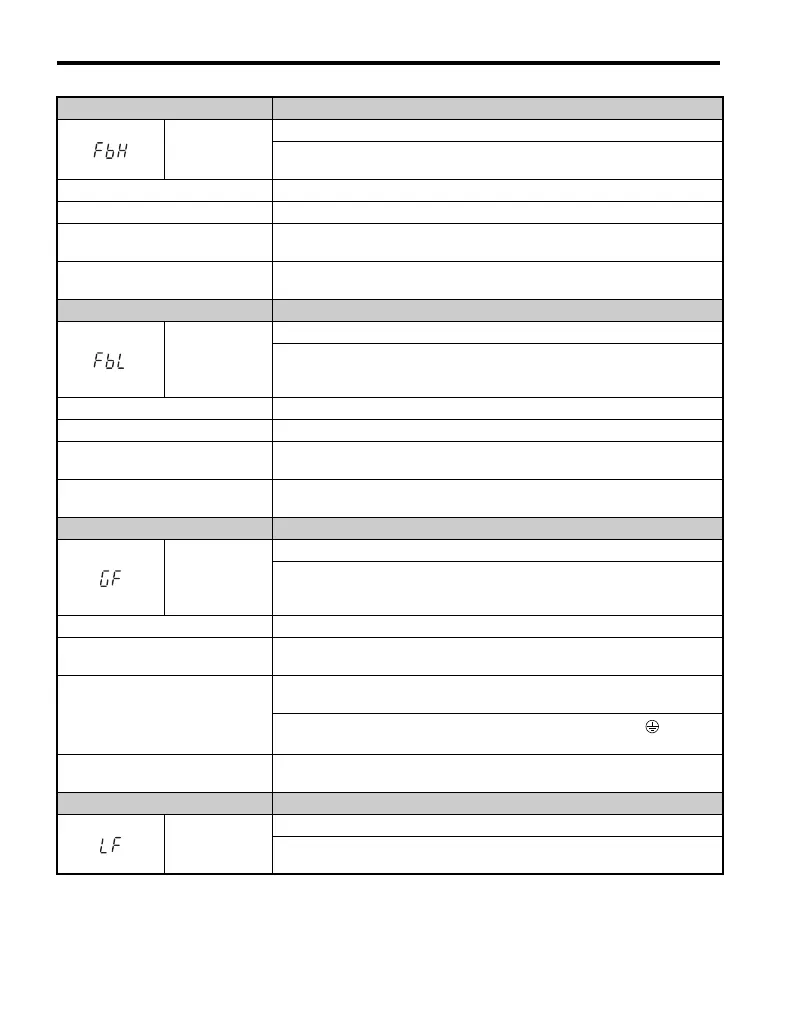
LED Operator Display Fault Name
FbH
Excessive PID Feedback
PID feedback input is greater than the level set b5-36 for longer than the time
set to b5-37. To enable fault detection, set b5-12 = “2” or “5”.
Cause Possible Solution
Parameters are not set appropriately. Check the settings of parameters b5-36 and b5-37.
Wiring for PID feedback is
incorrect.
Correct the wiring.
There is a problem with the
feedback sensor.
• Check the sensor on the control side.
• Replace the sensor if damaged.
LED Operator Display Fault Name
FbL
PID Feedback Loss
This fault occurs when PID Feedback Loss Detection is programmed to fault
(b5-12 = 2) and the PID Feedback < PID Feedback Loss Detection Level
(b5-13) for the PID Feedback Loss Detection Time (b5-14).
Cause Possible Solution
Parameters are not set appropriately. Check the settings of parameters b5-13 and b5-14.
Wiring for PID feedback is
incorrect.
Correct the wiring.
There is a problem with the
feedback sensor.
Check the sensor on the controller side.
If damaged, replace the sensor.
LED Operator Display Fault Name
GF
Ground Fault
• Current shorted to ground has exceeded 50% of the rated current on the output
side of the drive.
• Set L8-09 = “1” in order to enable ground fault detection on some models.
Cause Possible Solution
Motor insulation is damaged.
• Check the insulation resistance of the motor.
• Replace the motor.
A damaged motor cable is creating a
short circuit.
• Check the motor cable.
• Remove the short circuit and turn the power back on.
• Check the resistance between the cable and the ground terminal .
• Replace the cable.
The leakage current at the drive
output is too high.
• Reduce the carrier frequency.
• Reduce the amount of stray capacitance.
LED Operator Display Fault Name
LF
Output Phase Loss
• Phase loss on the output side of the drive.
• Phase Loss Detection is enabled when L8-07 is set to “1” or “2”.

 Loading...


