5.5 Fault Detection
220 YASKAWA TM.V1000.01 V1000 Drive Installation & Start-Up Manual (Preliminary 01-19-07)
Cause Possible Solution
The main circuit capacitors are
worn.
• Check the maintenance time for the capacitors (U4-05).
• Replace the drive if U4-05 is greater than 90%.
• Check for anything wrong with the drive input power.
• If nothing is wrong with the drive input power, try the following solutions if
the alarm continues:
• Disable Input Phase Loss Protection selection (L8-05 = “0”).
PF is detected if DC bus ripple is too high. If it is disabled, there is no fault but
the ripple is still too high, thereby the capacitors are stressed more and lose
lifetime.
• Replace the drive.
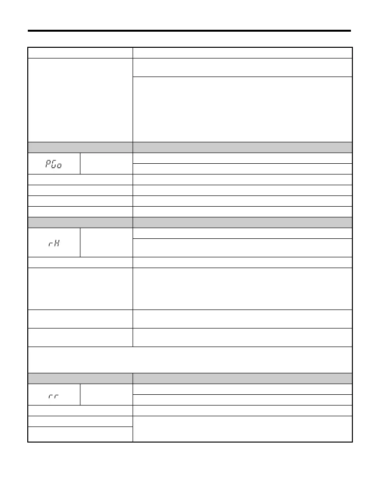
LED Operator Display Fault Name
PGo
PG Disconnect (for Simple V/f with PG)
No PG pulses are received for longer than the time set to F1-14.
Cause Possible Solution
Pulse input (RP) is disconnected. Reconnect the pulse input (RP).
Pulse input (RP) wiring is wrong. Correct the wiring.
Motor brake engaged. Ensure the motor brake releases properly.
LED Operator Display Fault Name
rH
Braking Resistor Overheat
Braking resistor protection was triggered.
Enabled when L8-01 = 1.
Cause Possible Solution
Deceleration time is too short and
excessive regenerative energy is
flowing back into the drive.
• Check the load, deceleration time and speed.
• Reduce the load.
• Increase the acceleration and deceleration times (C1-01 through C1-08).
• Replace the braking option with a larger device that can handle the power that
is discharged.
Excessive braking inertia.
Recalculate braking load and braking power. Then try reducing the braking
load and checking the braking resistor settings and improve braking capacity.
The proper braking resistor has not
been installed.
• Check the specifications and conditions for the braking resistor device.
• Select the optimal braking resistor.
Note: The magnitude of the braking load trips the braking resistor overheat alarm — NOT the surface temperature.
When the braking resistor is used more frequently than its rating, it trips the alarm even when the braking resistor
surface is not very hot.
LED Operator Display Fault Name
rr
Dynamic Braking Transistor
The built-in dynamic braking transistor failed.
Cause Possible Solution
The braking transistor is damaged. • Cycle power to the drive and check if the fault reoccurs. Refer to Using Fault
Trace Monitors on page 245.
• Replace the drive if the fault continues.
The control circuit is damaged.

 Loading...


