5.5 Fault Detection
222 YASKAWA TM.V1000.01 V1000 Drive Installation & Start-Up Manual (Preliminary 01-19-07)
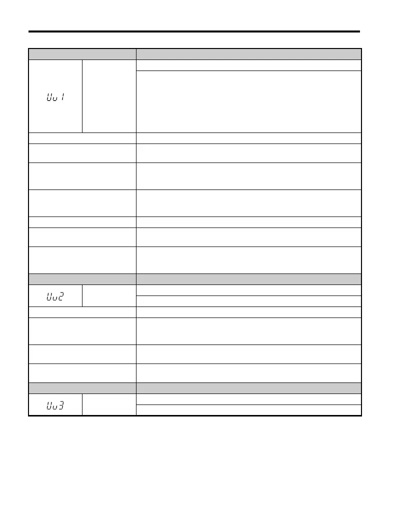
LED Operator Display Fault Name
Uv1
DC Bus Undervoltage
One of the following conditions occurred while the drive was stopped:
• The voltage in the DC bus fell below the undervoltage detection level
(L2-05).
• For 200 V class: approximately 190 V (160 V for single phase drives)
• For 400 V class: approximately 380 V (350 V when E1-01 is less then 400)
The fault is output only if L2-01 = 0 or L2-01 = 1 and the DC bus voltage is
under L1-05 for longer than L2-02.
Cause Possible Solution
Input power phase loss.
• The main circuit drive input power is wired incorrectly.
• Correct the wiring.
One of the drive input power wiring
terminals is loose.
• Ensure there are no loose terminals.
• Apply the tightening torque specified in this manual to fasten the terminals.
Refer to Wire Size and Torque Specifications on page 80
There is a problem with the voltage
from the drive input power.
• Check the voltage.
• Correct the voltage so that it is within the range listed in the drive input power
specifications.
The power has been interrupted. Correct the drive input power.
Drive internal circuitry has become
worn.
• Check the maintenance time for the capacitors (U4-05).
• Replace the drive if U4-05 exceeds 90%.
The drive input power transformer is
not large enough and voltage drops
after switching on power.
Check the capacity of the drive input power transformer.
LED Operator Display Fault Name
Uv2
Undervoltage
Voltage is too low for the control drive input power.
Cause Possible Solution
Parameter L2-02 (Momentary
Power Loss Ride-thru Time) has
changed from its default value.
Correct the setting of parameter L2-02.
The wiring for the control power
supply is damaged.
• Cycle power to the drive. Check if the fault reoccurs.
• Replace the drive if the fault continues to occur.
Internal circuitry is damaged.
• Cycle power to the drive. Check if the fault reoccurs.
• Replace the drive if the fault continues to occur.
LED Operator Display Fault Name
Uv3
Undervoltage 3 (Inrush Prevention Circuit Fault)
The inrush prevention circuit has failed.

 Loading...


