5.6 Alarm Detection
228 YASKAWA TM.V1000.01 V1000 Drive Installation & Start-Up Manual (Preliminary 01-19-07)
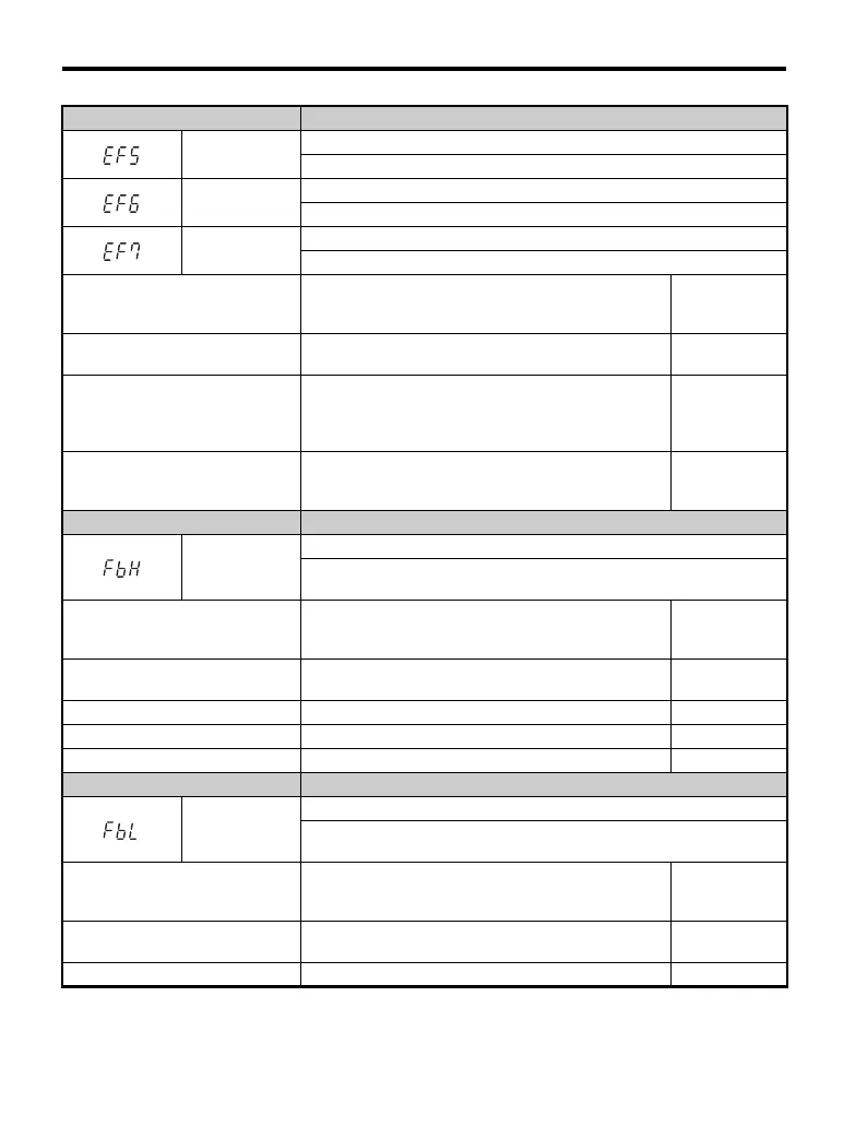
LED Operator Display Minor Fault Name
EF5
External fault (input terminal S5)
External fault at multi-function input terminal S5.
EF6
External fault (input terminal S6)
External fault at multi-function input terminal S6.
EF7
External fault (input terminal S7)
External fault at multi-function input terminal S7.
Cause Possible Solutions
Minor Fault
Output
(H2- = 10)
An external device has tripped an
alarm function.
Remove the cause of the external fault and reset the
multi-function input value.
YES
Wiring is incorrect.
• Ensure the signal lines have been connected properly to
the terminals assigned for external fault detection
(H1- =20to2F).
• Reconnect the signal line.
YES
Multi-function contact inputs are set
incorrectly.
• Check if the unused terminals have been set for
H1- =20to2F (External Fault).
• Change the terminal settings.
YES
LED Operator Display Minor Fault Name
FbH
Excessive PID Feedback
The PID feedback input is higher than the level set in b5-36 for longer than
the time set in b5-37, and b5-12 is set to 1 or 4.
Cause Possible Solutions
Minor Fault
Output
(H2- = 10)
Parameters settings for b5-36 and b5-
37 are incorrect.
Check parameters b5-36 and b5-37. YES
PID feedback wiring is faulty. Correct the wiring. YES
Feedback sensor has malfunctioned. Check the sensor and replace it if damaged. YES
Feedback input circuit is damaged. Replace the drive. YES
LED Operator Display Minor Fault Name
FbL
PID Feedback Loss
The PID feedback input is lower than the level set in b5-13 for longer than the
time set in b5-14, and b5-12 is set to 1 or 4.
Cause Possible Solutions
Minor Fault
Output
(H2- = 10)
Parameters settings for b5-13 and
b5-14 are incorrect.
Check parameters b5-13 and b5-14. YES
PID feedback wiring is faulty. Correct the wiring. YES

 Loading...


