7.4 Installing Peripheral Devices
YASKAWA TM.V1000.01 V1000 Drive Installation & Start-Up Manual (Preliminary 01-19-07) 307
Peripheral Devices &
Options
7
The influences depend on the frequency of the current, the higher the frequency
and the lower the rated trigger level/adjustment range of the protection device, the
higher is the lowering of the trigger level.
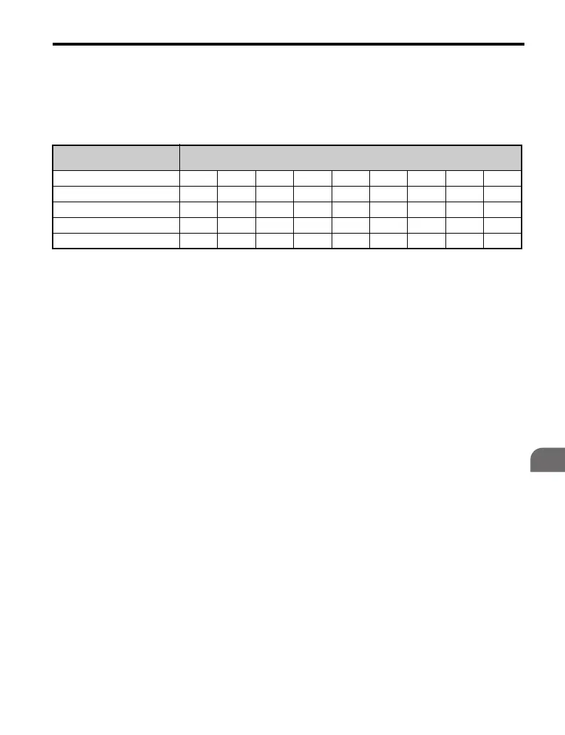
Table 7.3 Motor Protection Device Correction Factors
Example: A circuit breaker with an adjustment range of 1.1 to 1.6 A is used with a
drive working with 8 kHz carrier frequency. The motor rated current is 1.2 A. The
circuit breaker has to be adjusted to: 1.2 A x 1.21 = 1.45 A
Due to the harmonics the r.m.s. value of the motor current can be higher than the
rated motor current. In this case the circuit breaker can trigger unintentionally. To
prevent this, measure the motor current at rated load and redo the adjustment
correction
2. Influences of capacitive leakage currents. In some installations with very long
cables and high switching frequencies, there are capacitive leakage currents
flowing to through the protection device as well. These currents increase the
current flowing through the trigger and thereby lower the motor current value at
which the circuit breaker triggers. In this case the trigger level has to be increased
additionally to the procedure described in point 1.
3. Influence of the V/f pattern. If, for instance, a linear V/f pattern is set in the drive
and the output frequency is lower than the base frequency while the torque
decreases, it can happen, that the current becomes higher than the rated motor
current since the motor is over magnetized. Thereby it can happen, that the
protection device triggers unintentionally. This can not be compensated by
changing the trigger level of the protection device. Here it might help, if the V/f
pattern is changed to a quadratic V/f pattern.
Adjustment Range/ Rated
Current
Carrier Frequency
0 2 4 6 8 10 12 14 16
3.2 to 50 A 1.00 1.07 1.12 1.16 1.18 1.19 1.21 1.22 1.23
0.5 to 2.5 A 1.00 1.08 1.13 1.17 1.21 1.24 1.26 1.28 1.29
0.32 to 0.4 A 1.00 1.09 1.15 1.21 1.25 1.29 1.33 1.35 1.37
0.16 to 0.25 A 1.00 1.10 1.17 1.24 1.28 1.33 1.38 1.42 1.46

 Loading...


