B.2 Parameter Table
YASKAWA TM.V1000.01 V1000 Drive Installation & Start-Up Manual (Preliminary 01-19-07) 383
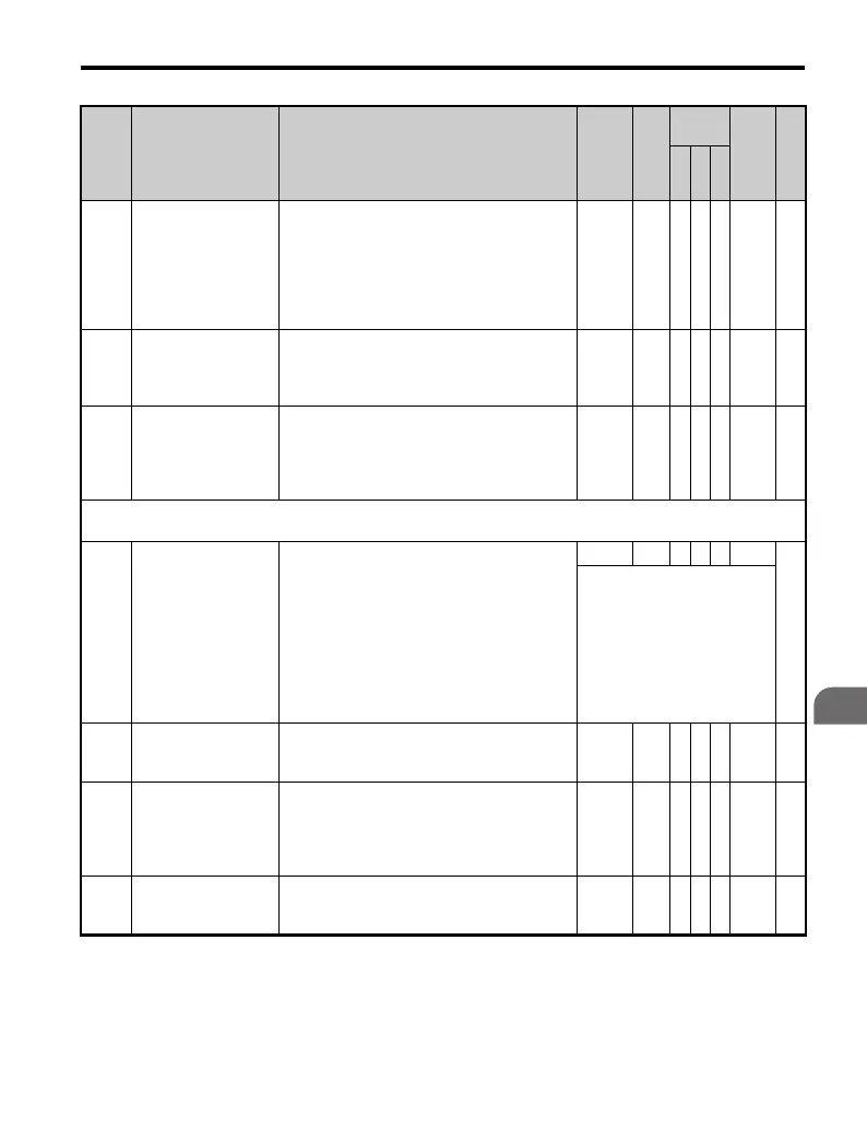
Parameter List
B
L1-04
Motor Overheat Fault
Operation Selection
(PTC input)
Sets stopping method when the motor
temperature analog input
(H3-02 or H3-10 = E) exceeds the OH4 fault
level (2.34V).
0: Ramp to Stop
1: Coast to Stop
2: Fast-stop
0 to 2 1 A A A 483 —
L1-05
Motor Temperature
Input Filter Time
(PTC input)
This parameter adjusts the filter on the motor
temperature analog input
(H3-02 or H3-10 = E). Increase to add stability,
decrease to improve response.
0.00 to
10.00
0.20
s
A A A 484 —
L1-13
Continuous
Electrothermal
Operation Selection
Determines whether or not to hold the
electrothermal value when the power supply is
interrupted.
0: Disabled
1: Enabled
0 to 1 1 A A A 46D —
L2: Momentary Power Loss
Use L2 parameters to configure drive functions for momentary power loss conditions.
L2-01
Momentary Power
Loss Operation
Selection
Enables and disables the momentary power
loss function.
0: Disabled - Drive trips on (UV1) fault when
power is lost.
1: Power Loss Ride-Thru Time - Drive will
restart if power returns within the time set in
L2-02.
2: CPU Power Active - Drive will restart if
power returns prior to control power supply
shut down.
0 to 2 0 A A A 485
—
For a restart to occur, the run
command must be maintained
throughout the ride-thru
period.
L2-02
Momentary Power
Loss Ride-Thru Time
Sets the Power Loss Ride-Thru time. This
value is dependent on the drive capacity. Only
effective when L2-01 = 1.
0.0 to
25.5
<12> A A A 486 —
L2-03
Momentary Power
Loss Minimum
Baseblock Time
Sets the minimum wait time for residual motor
voltage decay before the drive output
reenergizes after power loss ride-thru. After a
power loss, if L2-03 is greater than L2-02,
operation resumes after the time set in L2-03.
0.1 to
5.0
<12> A A A 487 —
L2-04
Momentary Power
Loss Voltage
Recovery Ramp Time
Sets the time for the output voltage to return to
the preset V/f pattern after speed search
(current detection mode) is complete.
0.0 to
5.0
<12> A A A 488 —
No. Name Description Range Def.
Control
Mode
Addr.
Hex
Pg.
V/
f
O
L
V
P
M

 Loading...


