B.2 Parameter Table
YASKAWA TM.V1000.01 V1000 Drive Installation & Start-Up Manual (Preliminary 01-19-07) 387
Parameter List
B
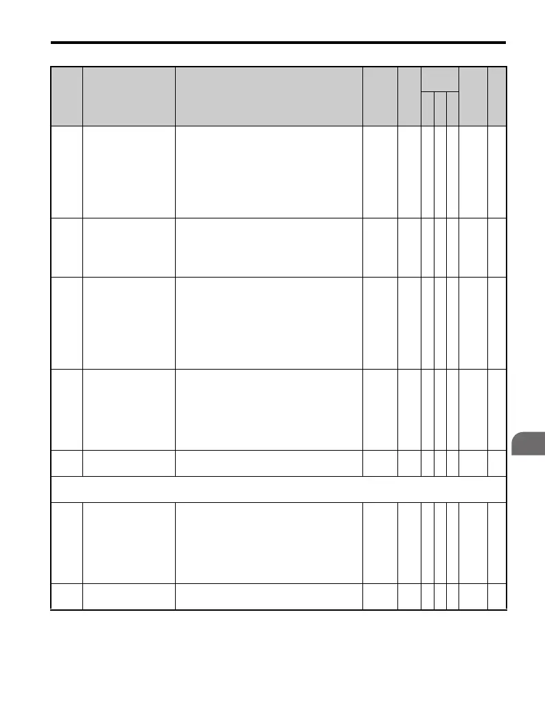
L3-21
Accel/Decel Rate
Calculation Gain
Sets the proportional gain used to calculate the
deceleration rate during KEB, OV suppression
function, and stall prevention during
deceleration (L3-04 = 2).
This parameter does not typically require
adjustment.
Increase the value gradually in units of 1.0 if
overcurrent and overvoltage occur.
0.00 to
200.00
1.00 A A A 466 —
L3-22
Deceleration Time at
Stall Prevention
during Acceleration
For use with a PM motor. Sets the deceleration
time used for stall prevention during
acceleration.
When set to 0, the drive decelerates at the
normal deceleration time.
0.0 to
6000.0
0.0 s −−A4F9 —
L3-23
Automatic Reduction
Selection for Stall
Prevention during
Run
0: Sets the stall prevention level throughout the
entire frequency range to the value in
parameter L3-06.
1: Automatically lowers the stall prevention
level in the constant output range (output
frequency is greater than the max voltage
output frequency). The lower limit value is
40% of L3-06.
0, 1 0 A A Α 4FD —
L3-24
Motor Acceleration
Time for Inertia
Calculations
Sets the time needed to accelerate the
uncoupled motor at rated torque from stop to
the maximum frequency.
This parameter does not typically require
adjustment. Setting the drive capacity to
parameter o2-04 will automatically set this
parameter for a 4-pole motor.
0.001 to
10.000
<12> A A A 46E —
L3-25 Load Inertia Ratio
Sets the ratio between the connected
machinery and the motor.
0.0 to
1000.0
1.0 A A A 46F —
L4: Frequency Detection
Use L4 parameters to configure frequency detection operation.
L4-01
Speed Agreement
Detection Level
These parameters configure the multi-function
output (H2- = 2, 3, 4, 5) settings "Fref/
Fout Agree 1", "Fref/Set Agree 1", "Frequency
Detection 1," and "Frequency detection 2".
Parameter L4-01 sets the level while parameter
L4-02 sets the hysteresis for the Speed
Detection Output Function.
0.0 to
400.0
0.0
Hz
A A A 499 —
L4-02
Speed Agreement
Detection Width
Refer to L4-01.
0.0 to
20.0
2.0
Hz
A A A 49A —
No. Name Description Range Def.
Control
Mode
Addr.
Hex
Pg.
V/
f
O
L
V
P
M

 Loading...


